Demand/supply control device, demand/supply control methodm, and demand/supply control system

a control device and control method technology, applied in the direction of process and machine control, greenhouse gas reduction, instruments, etc., can solve the problems of not only temporal mismatching, but quantitative mismatching, and the inability to generate electric power to meet the demand of a building, so as to avoid the (large) loss of energy of surplus electric power, reduce operating costs, and improve the use efficiency of surplus electric power

Active Publication Date: 2012-03-22
PANASONIC INTELLECTUAL PROPERTY MANAGEMENT CO LTD
View PDF10 Cites 34 Cited by
  • Summary
  • Abstract
  • Description
  • Claims
  • Application Information

AI Technical Summary

Benefits of technology

[0019]With such a configuration, the operating cost can be sufficiently reduced even when there are energy storage means for storing electricity, heat, and others.
[0020]For example, it is possible to avoid the (large) loss in energy of surplus electric power, improve the use efficiency of the surplus electric power, and reduce the operating cost by storing

Problems solved by technology

However, there is a problem that electric power cannot be generated to meet the demand of a building, because the solar power system is subject to a weather and others and the electrical power output is mainly determined by light energy generated by the sun.
This is because in g

Method used


Image

  • Demand/supply control device, demand/supply control methodm, and demand/supply control system
  • Demand/supply control device, demand/supply control methodm, and demand/supply control system
  • Demand/supply control device, demand/supply control methodm, and demand/supply control system

Examples


embodiment 1

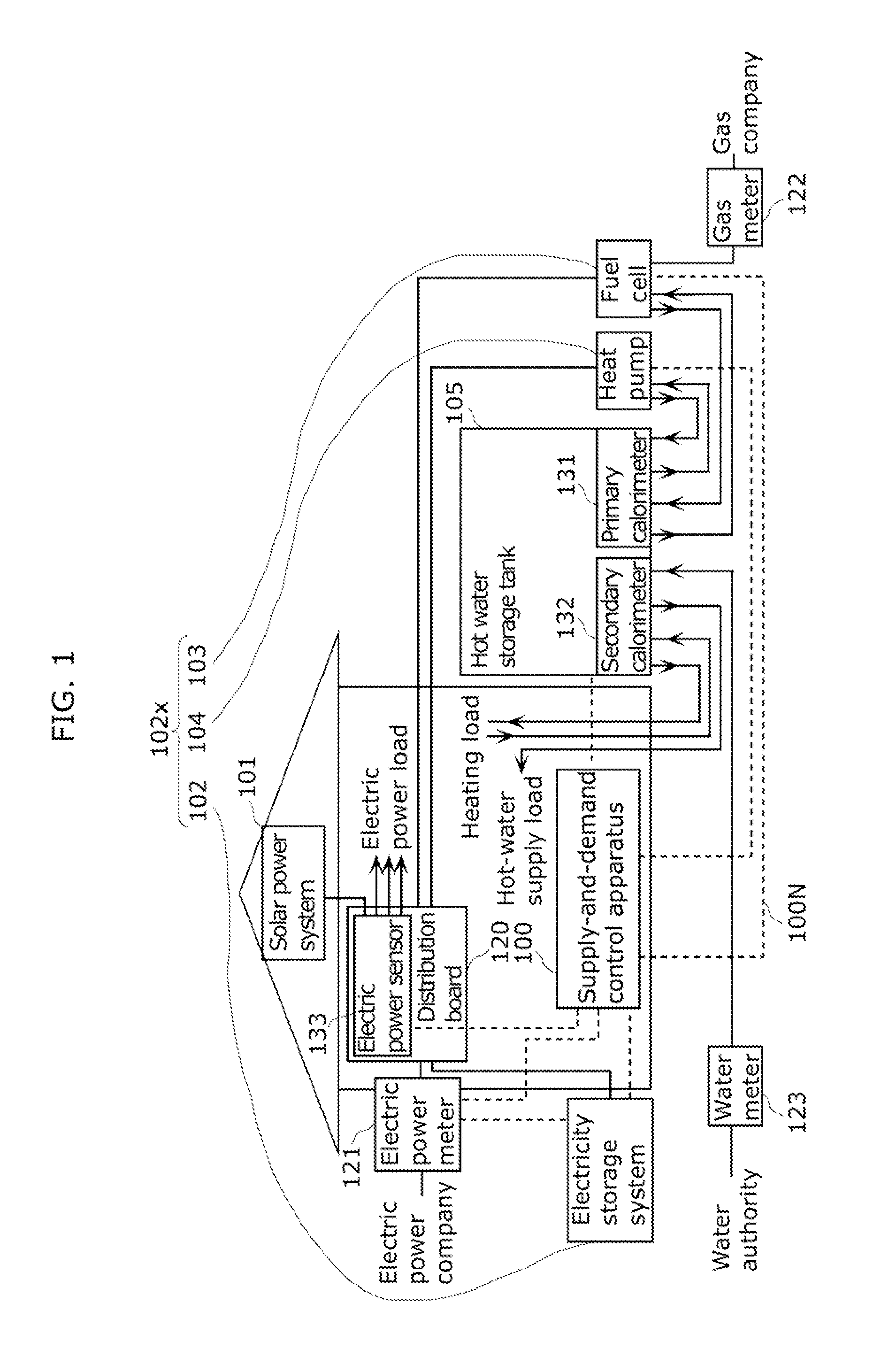
[0071]FIG. 1 illustrates an example of a configuration of an energy supply system according to Embodiment 1.

[0072]The energy supply system is installed in buildings, such as a house and an office building. The electric power is supplied to a device that operates using electric power (electric power load), while two energies of electric power and hot water are supplied to a device that uses the hot water (hot-water supply load), such as a water heater, and to a device for heating using heat of the hot water (heating load).

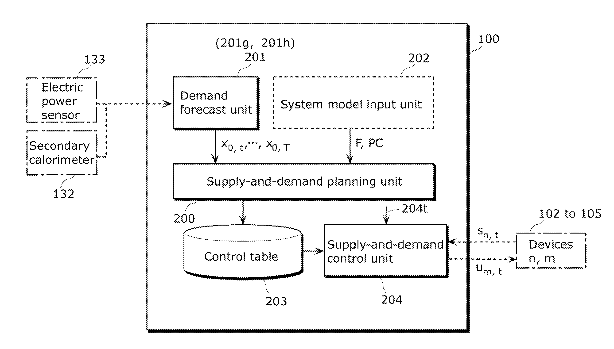
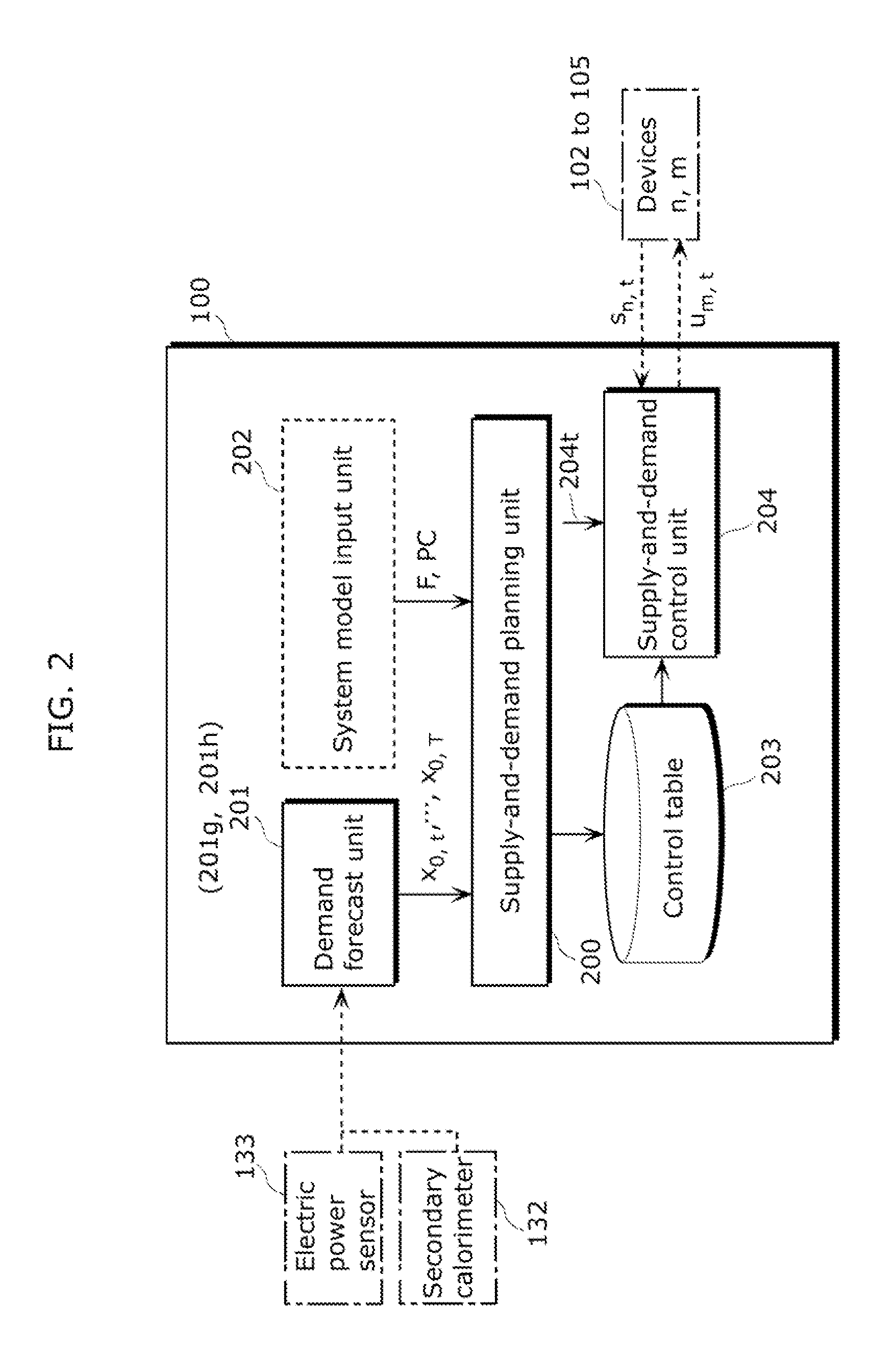
[0073]The energy supply system in FIG. 1 includes a solar power system 101, an electricity storage system (storage battery system) 102, a fuel cell 103, a heat pump 104, and a hot water storage tank 105. Furthermore, the energy supply system includes a distribution board 120, an electric power meter 121, a gas meter 122, and a water meter 123. Furthermore, the energy supply system includes a supply-and-demand control apparatus 100 for efficiently operating these con...

embodiment 2

[0148]FIG. 5 illustrates an example of a configuration of an energy supply system according to Embodiment 2. The energy supply system according to Embodiment 2 differs from that according to Embodiment 1 by having no fuel cell 103 that exists in FIG. 1. Here, an energy device 102y includes an electricity storage system 102 and a heat pump 104.

[0149]According to Embodiment 1, the vector st is a three-dimensional vector representing an amount of stored energy, an amount of stored heat, and an operating state of a fuel cell (see the second to fourth columns in FIG. 3). According to Embodiment 2, the vector st is a two-dimensional vector representing an amount of stored energy and an amount of stored heat because no fuel cell exists (see the second to third columns in FIG. 7).

[0150]In this case, a path of the two-dimensional vector is easily illustrated. Here, FIG. 6 illustrates the path of the two-dimensional vector with the electricity stored in the horizontal axis and the amount of h...

embodiment 3

[0243]FIG. 13 illustrates a configuration of an energy supply-and-demand system according to Embodiment 3.

[0244]FIG. 14 illustrates a detailed configuration of the energy supply-and-demand system.

[0245]In addition to the configuration according to Embodiments 1 and 2, the energy supply system according to Embodiment 3 includes a server (cloud server, optimal supply-and-demand apparatus, the first supply-and-demand control apparatus) 100a and a supply-and-demand control apparatus (the second supply-and-demand control apparatus) 300, and the server 100a is connected to the supply-and-demand control apparatus 300 through a communication line 100n as illustrated in FIGS. 13 and 14.

[0246]According to Embodiment 3, not the supply-and-demand control apparatus 300 but the server 100a forecasts a demand (see Sj2 in FIG. 4 and Ss2 in FIG. 15 to be described later) and generates a control parameter (Sj3, Ss3).

[0247]Then, communication between the supply-and-demand control apparatus 300 and the...


PUM


Abstract

The supply-and-demand control apparatus (100) includes: an obtaining unit (201g) that obtains power consumption and heat consumption; a forecast processing unit (201h) that obtains demand forecast data on each of electric power and an amount of heat using the power consumption and heat consumption, respectively; a supply-and-demand planning unit (200) that calculates a control parameter (the fourth and fifth columns in FIG. 7) for controlling operations of an electricity storage system (102) and a heat pump (104) that supplies heat to a hot water storage tank (105), by substituting the calculated demand forecast data into a predetermined function; and a supply-and-demand control unit (204) that controls the operations using the control parameter, wherein the supply-and-demand planning unit (200) calculates the control parameter such that electric power generated by a solar power system (101) is distributed to the electricity storage system (102) and the heat pump (104).

Description

TECHNICAL FIELD[0001]The present invention relates to a supply-and-demand control apparatus, a supply-and-demand control method, and a supply-and-demand control system for calculating an operation plan of an electricity storage device that discharges and charges electric power and a heat source device that supplies heat, in a system that controls operations of the electricity storage device and the heat source device.BACKGROUND ART[0002]Conventionally, systems have been studied which operate apparatuses installed in buildings, such as a house and an office building, using renewable energies, such as sunlight, wind power, and geothermal heat. Each of the systems includes an electricity storage device that discharges and charges electric power generated using a renewable energy, and a heat source device that generates heat using city gas or air. With efficient operations of the electricity storage device or the heat source device, it is possible to reduce CO2 discharged by the energy ...

Claims


Application Information

Patent Timeline
IPC IPC(8): G06F1/28
CPCH02J3/14H02J3/32H02J2001/004H02J2003/003H02J2003/146Y04S20/244Y02B70/3225Y02B70/3275Y04S20/222Y04S20/224Y02E70/30H02J2300/30H02J2310/64H02J3/003H02J2310/14Y04S50/10Y04S20/242Y02B70/30
Inventor KAJI, MITSURU
Owner PANASONIC INTELLECTUAL PROPERTY MANAGEMENT CO LTD
Why Eureka
Try Eureka