Co2 refrigeration system for ice-playing surfaces

a refrigeration system and ice-playing technology, applied in water-skiing, sports equipment, ski bindings, etc., can solve the problems of high flammability of refrigerants, environmental harm, and high risk of local safety

Inactive Publication Date: 2012-03-29
TOROMONT INDS
View PDF7 Cites 15 Cited by
  • Summary
  • Abstract
  • Description
  • Claims
  • Application Information

AI Technical Summary

Problems solved by technology

Although ammonia and hydrocarbons have negligible ozone-depletion potential and global-warming potential as does CO2, these refrigerants are highly flammable and therefore represent a risk to local safety.
However, these refrigeration circuits often use refrigerants that are harmful to the environment.

Method used


Image

  • Co2 refrigeration system for ice-playing surfaces
  • Co2 refrigeration system for ice-playing surfaces
  • Co2 refrigeration system for ice-playing surfaces

Examples


Embodiment Construction

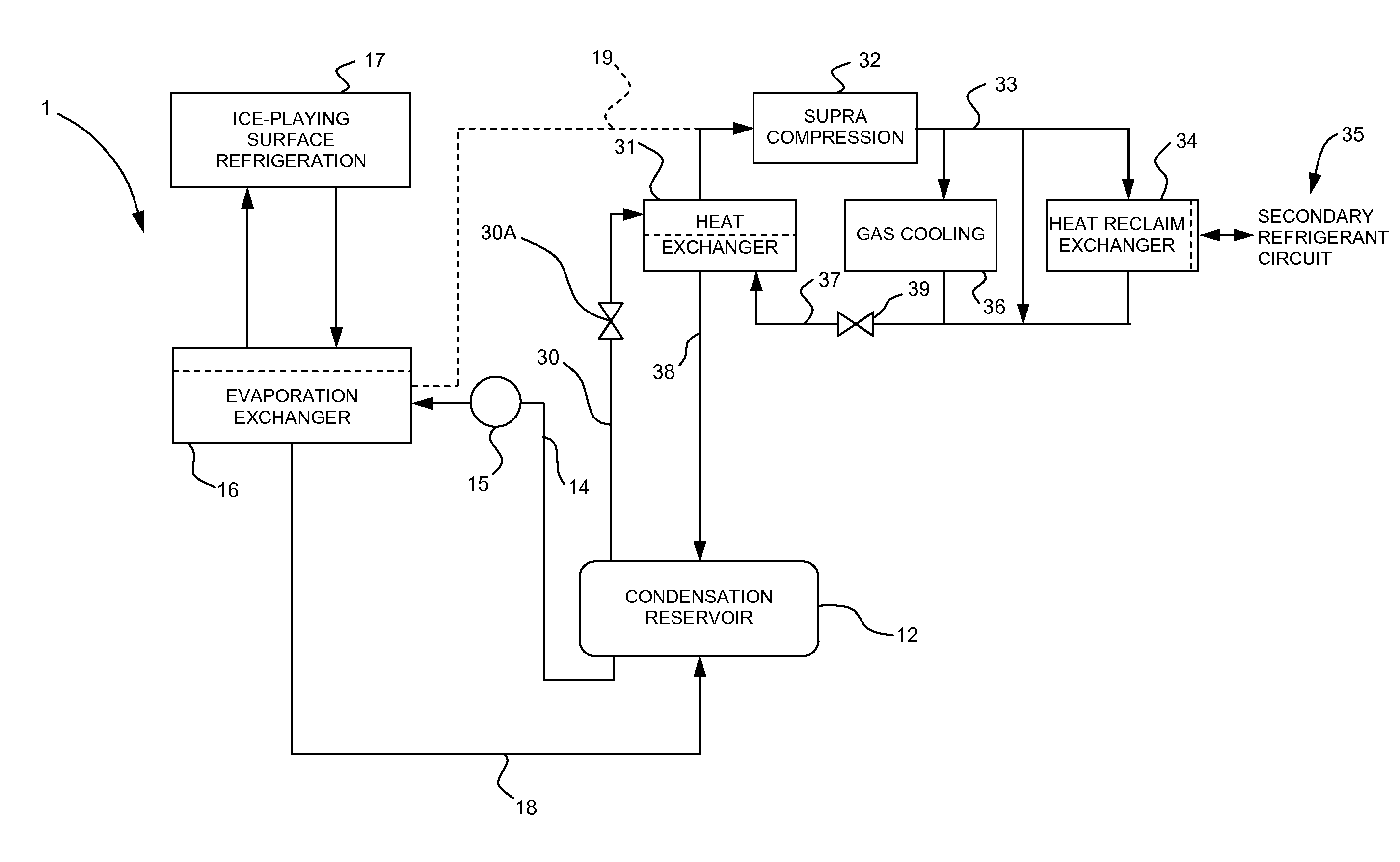
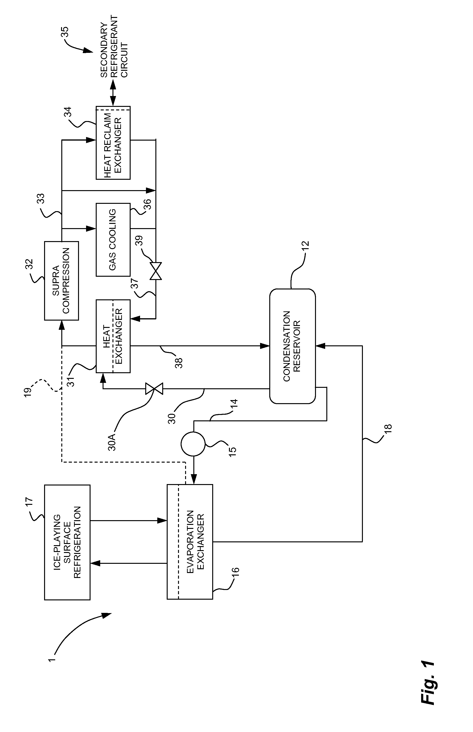
[0015]Referring to FIG. 1, a CO2 refrigeration system in accordance with an embodiment is illustrated at 1. The CO2 refrigeration system 1 has a CO2 refrigeration circuit comprising a CO2 condensation reservoir 12. The condensation reservoir 12 accumulates CO2 refrigerant in a liquid and gaseous state, and may be in a heat-exchange relation with a closed condensation circuit that absorbs heat from the CO2 refrigerant, with examples given hereinafter.

[0016]Line 14 directs CO2 refrigerant from the condensation reservoir 12 to an evaporation stage via pump(s) or expansion valve(s). As is shown in FIG. 1, the CO2 refrigerant is supplied in a liquid state by the condensation reservoir 12 into line 14. The pump 15 ensures a suitable flow of liquid CO2 refrigerant to the evaporation exchanger 16. In some instances, expansion valve(s) 15 may be used to control the pressure of the CO2 refrigerant, which is then fed to the evaporation exchanger 16. Any appropriate means may be used to put the...


PUM


Abstract

A CO2 refrigeration system comprises a condensation reservoir. CO2 refrigerant is accumulated in the reservoir. The CO2 refrigerant circulates between supracompression and evaporation loops. The supracompression loop comprises a compression stage for compression CO2 refrigerant to a supracompression state, a cooling stage in which CO2 refrigerant releases heat, and a pressure-regulating unit in a line extending from the cooling stage to the condensation reservoir. The pressure-regulating unit maintains a pressure differential between the cooling stage and the condensation reservoir. The evaporation loop comprises an evaporation stage in which CO2 refrigerant from the condensation reservoir absorbs heat in a heat exchanger. The heat exchanger is connected to an ice-playing surface refrigeration circuit. A second refrigerant cycles in the ice-playing surface refrigeration circuit. The CO2 refrigerant absorbs heat from the second refrigerant in the heat exchanger. A CO2 condensation exchanger is also provided.

Description

CROSS-REFERENCE TO RELATED APPLICATION(S)[0001]The present application claims the benefit of U.S. Provisional Patent Applications No. 61 / 387,087, filed on Sep. 28, 2010, and No. 61 / 415,982, filed on Nov. 22, 2010. The present application claims priority on Canadian Patent Application No. 2,724,255, filed on Dec. 17, 2010, now Canadian Patent No. 2,724,255, issued on Sep. 13, 2011, all of the above incorporated herein by reference.FIELD OF THE APPLICATION[0002]The present application relates to refrigeration systems used in industrial refrigeration applications, such as rinks, curling centers and arenas, to refrigerate an ice-skating or ice-playing surface, and more particularly to such refrigeration systems using CO2 refrigerant.BACKGROUND OF THE ART[0003]With the growing concern for global warming, the use of chlorofluorocarbons (CFCs) and hydrochlorofluorocarbons (HCFCs) as refrigerant has been identified as having a negative impact on the environment. These chemicals have non-neg...

Claims


Application Information

Patent Timeline
Patent Type & Authority Applications(United States)
IPC IPC(8): A63C19/10F25B1/00
CPCF25B9/008F25B25/005F25B2309/061F25B30/06F25B29/003F25B31/00F25C3/02
Inventor DUBE, SERGE
Owner TOROMONT INDS
Why Eureka
Try Eureka