Fuel Injection Feedback System and Method

a feedback system and fuel injection technology, applied in the direction of machines/engines, electric control, instruments, etc., can solve the problems of high cost of in-cylinder pressure transducers, inability to accurately predict the timing of injection, so as to facilitate the installation of one or more strands

Active Publication Date: 2012-03-29
CUETO OMAR
View PDF7 Cites 25 Cited by
  • Summary
  • Abstract
  • Description
  • Claims
  • Application Information

AI Technical Summary

Benefits of technology

[0012]In another embodiment, the light source and optical sensor comprise a fiber optic assembly. That is, the light source comprises an emitting fiber optic, and the optical sensor comprises a detecting fiber optic. In this embodiment, fiber optic conduits are drilled into the body to facilitate installation of one or more strands of fiber optics. The nozzle cap and needle are also drilled as needed to create additional conduits for installation of fiber optic fibers.

Problems solved by technology

Advanced combustion engines are very sensitive to injection timing and combustion and require continuous adjustment of ignition timing.
Laboratory research engines studying advanced combustion typically use in-cylinder pressure transducers, which are expensive and require space in the combustion chamber.

Method used


Image

  • Fuel Injection Feedback System and Method
  • Fuel Injection Feedback System and Method
  • Fuel Injection Feedback System and Method

Examples


Embodiment Construction

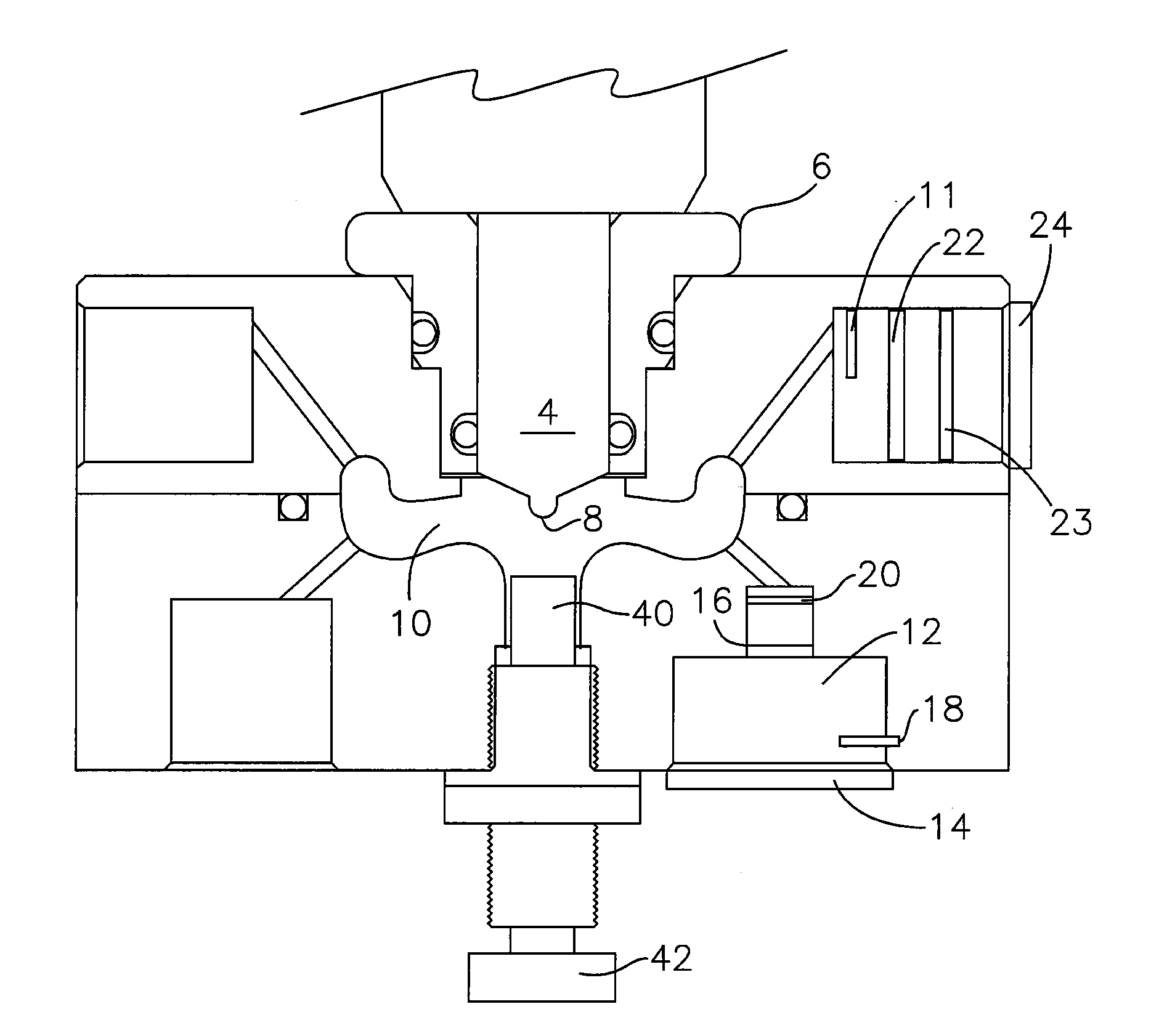
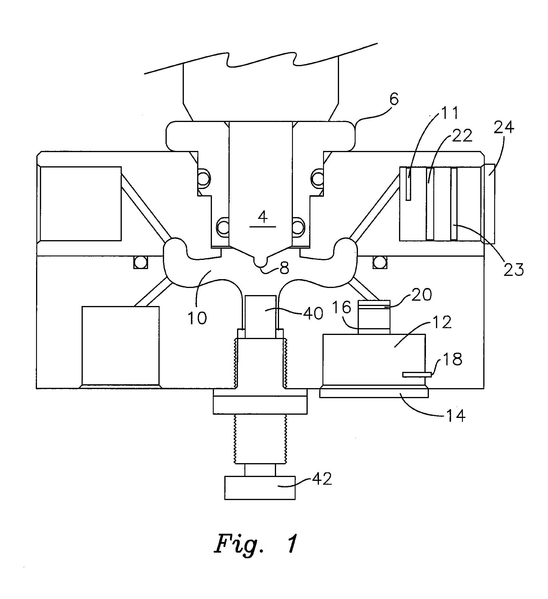
[0032]Disclosed is both an apparatus and method for quantifying an injection event including both multiple pulse and single pulse injection events. The apparatus includes a pressure chamber for isolating a portion of the injection event. By isolating the event, the apparatus reduces the pressure waves and reflections which can create “noise” in detecting the injection pressure. The apparatus may further include detecting the start and stop times of injection using an optical timing device based upon the opaque properties of cavitation.

[0033]While the present apparatus and method are especially advantageous when implemented to measure fuel injection quantity, variation, and / or rate of multi-pulse injections, such may also be used to measure the parameters of fuel injectors operable in a conventional, single injection pulse manner. As can be appreciated by one of ordinary skill in the art, multi-pulse common rail injection systems may be operated in a conventional manner to provide a ...


PUM


Abstract

A fuel injection feedback system comprises a light source disposed inside a fuel injector, an optical sensor disposed inside the fuel injector, and a computing device electronically connected to the optical sensor. The light source is a device configured to emit light capable of being reflected by cavitation. The light source could be disposed on or within the needle or nozzle of the fuel injector, or at a variety of other locations inside the fuel injector. The optical sensor is configured to detect an intensity of light caused by receiving light reflected from cavitation occurring inside the fuel injector.

Description

RELATED APPLICATION[0001]This application is a continuation-in-part of U.S. patent application Ser. No. 13 / 153,417, filed Jun. 21, 2011, which is a divisional of U.S. patent application Ser. No. 12 / 233,615, filed Sep. 19, 2008, now U.S. Pat. No. 7,975,535.TECHNICAL FIELD[0002]The present invention relates to an system and method for obtaining feedback from a fuel injector. In greater detail, the present invention relates to a method and apparatus for determining the quantity and rate shape of injection by a fuel injector for monitoring the injector.BACKGROUND OF THE INVENTION[0003]In recent years, increasing concerns over fuel economy and environmental sensitivity have driven the transportation industry to develop new technologies to address these concerning issues. In fuel injection systems, fuel economy and emissions are driven by fuel injection characteristics. For example, the start, end, duration, and rate of fuel injection vary according to machining tolerances, aging, fuel pr...

Claims


Application Information

Patent Timeline
Patent Type & Authority Applications(United States)
IPC IPC(8): G01M15/04
CPCF02D41/40F02D2200/0614F02D2200/0618G01M15/04F02M65/001F02M2200/24F02M57/005
Inventor CUETO, OMAR
Owner CUETO OMAR
Why Eureka
Try Eureka