Water Actuated Pressurized Gas Release Device

a technology of pressure gas release device and water actuation, which is applied in the direction of vessel construction details, transportation and packaging, functional valve types, etc., can solve the problems of low cost, easy wear, and device work well, and achieve the effect of small siz

Active Publication Date: 2012-03-29
CARLETON TECH
View PDF1 Cites 8 Cited by
  • Summary
  • Abstract
  • Description
  • Claims
  • Application Information

AI Technical Summary

Benefits of technology

[0013]Still yet another advantage of the present invention is that it can be connected to inflation equipment via a rotatable ring, whereby the device can be connected in any of a variety of orientations, which adds both to the ease, convenience and acceptability of use as well as broadly useful with many different interfaces.
[0014]A further advantage of the present invention is that it can be fitted to a salinity sensor whereby the gas cartridge can be activated in the presence of fresh or salt water.
[0015]These and other advantages are provided by a device suitable for general commercial and individual recreational use that is automatically actuated to release gas from a pressurized gas cylinder when immersed in an electrically conductive fluid. In particular, the pressurized gas release device of the present invention has a relatively small size and is of a lightweight construction that does not hinder a person moving about. That way, the device can be worn on a belt or otherwise secured to a person's body as a personal effect and serves to automatically inflate a personal flotation device should the person inadvertently fall into fresh or salt water. The personal flotation device can be a life jacket, a life vest or a personal life raft. The potentially life-threatening drowning situation is thereby averted.

Problems solved by technology

These devices work well because they are easily worn by a pilot or by a seaman working around water.
However, there is a need for a low cost, lightweight, unobtrusive water-actuated pressurized gas release device for general commercial, military and / or individual recreational use which interfaces with a variety of flotation devices, vests, rafts, etc.
This prevents the device from being re-used because if a new cylinder is screwed into the body the locked forward piecing pin will puncture the cylinder as it is being it tightened.

Method used


Image

  • Water Actuated Pressurized Gas Release Device
  • Water Actuated Pressurized Gas Release Device
  • Water Actuated Pressurized Gas Release Device

Examples


Embodiment Construction

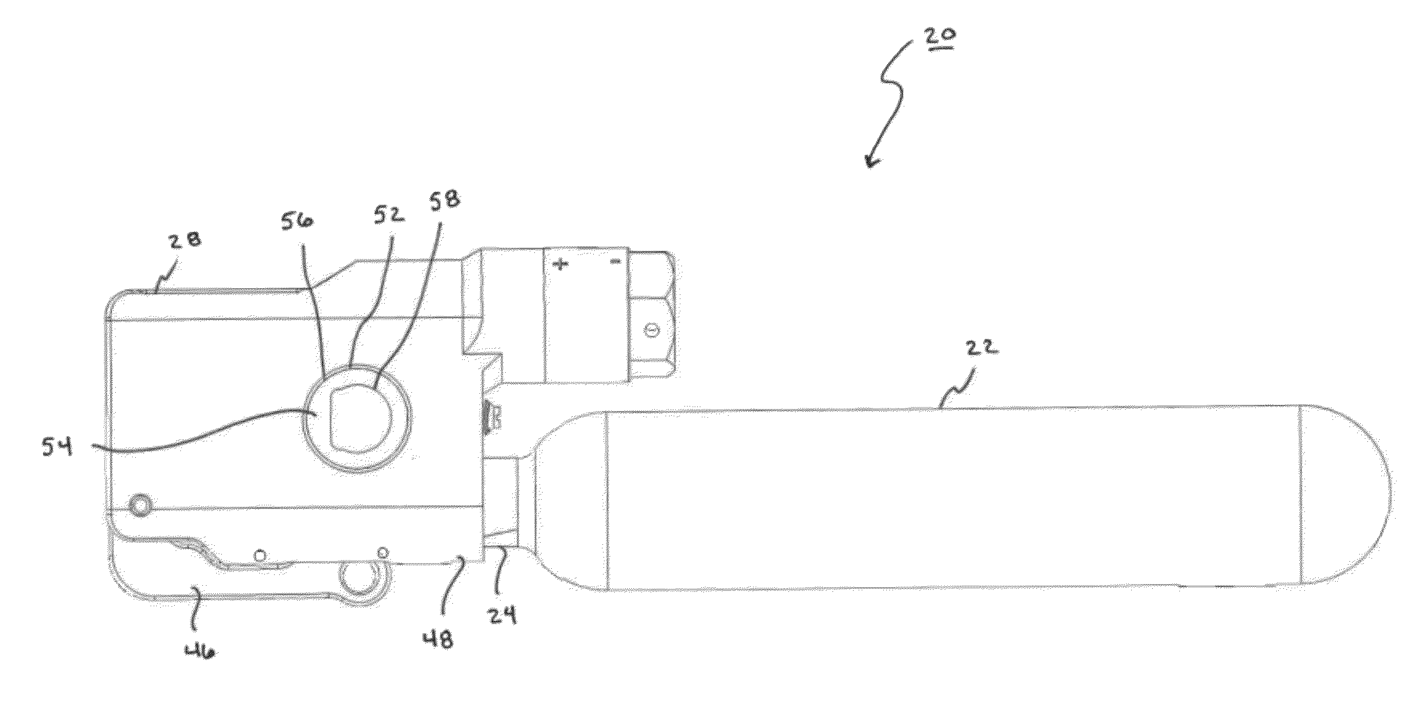
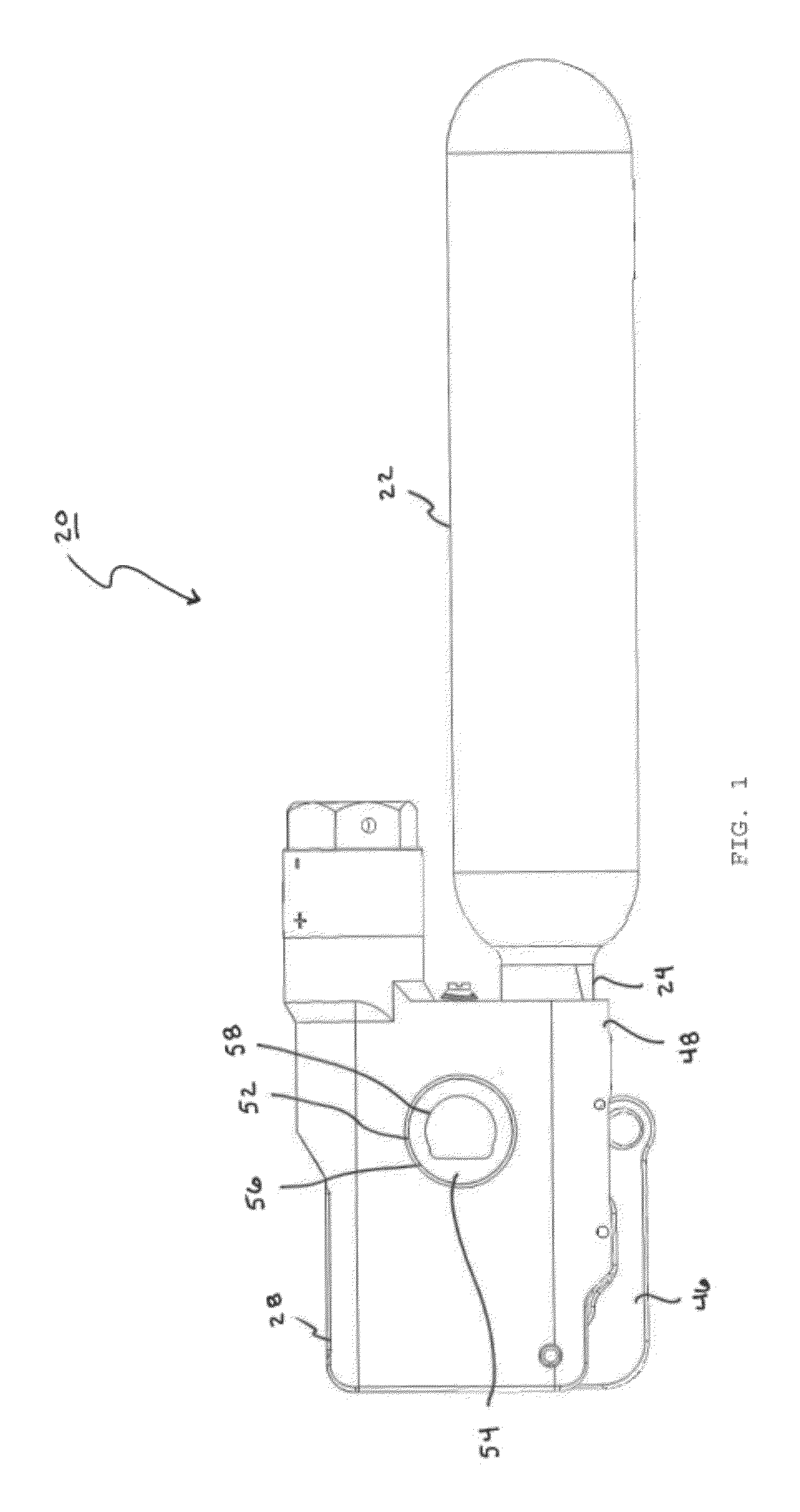
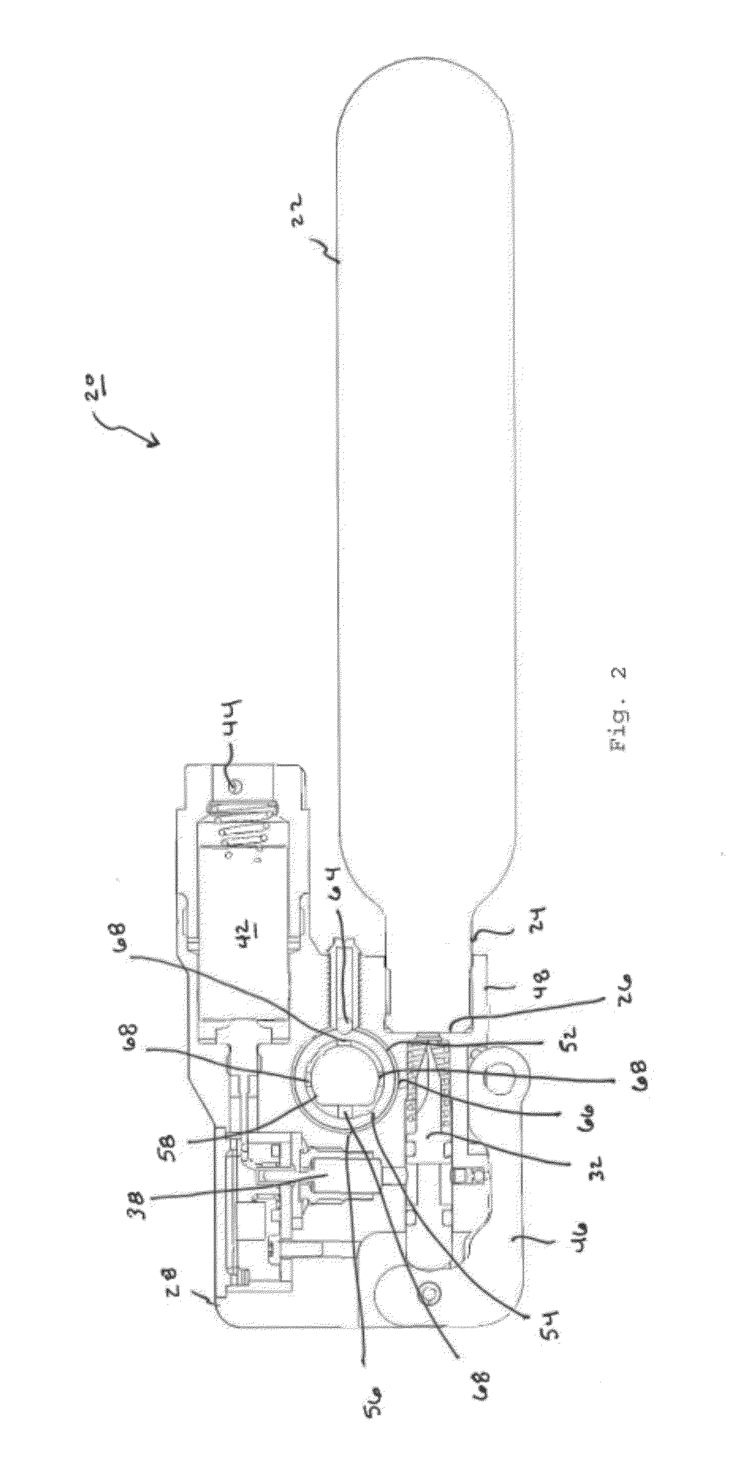
[0025]The present invention relates to a gas release device that is adapted to be secured to an inflatable article. The device includes an container, which can be a commercially available gas bottle, a salinity sensor, and an end cap. The salinity sensor operates an electrically fireable primer that serves to release an inflation gas from the container and inflate the article. The end cap includes a cylindrical through hole that accepts a rotatable D-ring. The D-ring is dimensioned to fit over the valve of the inflatable article. The D-ring includes a series of peripheral apertures that can be selectively aligned with a slot to create a fluid passage between the container and valve. The D-ring allows the device to be rotated between different angular positions while maintaining a pneumatic coupling between to the inflatable article and the container. In an alternative embodiment, the D-ring is replaced by a D-shaped keyway.

Gas Release Device

[0026]FIGS. 1-2 illustrate the gas release...


PUM


Abstract

Disclosed is a gas release device that is adapted to be secured to an inflatable article. The device includes an container, which can be a commercially available gas bottle, a salinity sensor, and an end cap. The salinity sensor operates an electrically fireable primer that serves to release an inflation gas from the container and inflate the article. The end cap includes a cylindrical through hole that accepts a rotatable D-ring. The D-ring is dimensioned to fit over the valve of the inflatable article. The D-ring includes a series of peripheral apertures that can be selectively aligned with a slot to create a fluid passage between the container and valve. The D-ring allows the device to be rotated between different angular positions while maintaining a pneumatic coupling between to the inflatable article and the container.

Description

CROSS-REFERENCE TO RELATED APPLICATIONS[0001]This application claims priority to, and is a continuation of, co-pending provisional application Ser. No. 61 / 382,271 filed on Sep. 13, 2010 and entitled “Water Actuated Pressurized Gas Release Device.” The contents of this co-pending application are fully incorporated herein for all purposes.BACKGROUND OF THE INVENTION[0002]1. Field of the Invention[0003]This invention relates to a gas release device. More particularly, the present invention relates to a gas release device that is activated by both fresh and salt water and that can be adjustably mounted upon flotation equipment.[0004]2. Description of the Background Art[0005]The use of pressurized gas release devices for inflating floatation equipment is known in the art. For example, U.S. Pat. No. 4,024,440 to Miller and U.S. Pat. No. 4,768,128 to Jankowiak et al, which are assigned to the assignee of the present invention and are incorporated herein by reference, describe water-actuate...

Claims


Application Information

Patent Timeline
Patent Type & Authority Applications(United States)
IPC IPC(8): F16K15/00
CPCB63C9/19B63C2009/007B63C2009/0047F17C1/00F17C2201/0109F17C2201/058F17C2203/0617F17C2205/032F17C2221/013F17C2221/016F17C2221/017F17C2223/0123F17C2223/036F17C2270/0181F17C2270/0772Y10T137/2036Y10T137/7722
Inventor CLARK, ROBERT E.FORD, BRIANKELLEY, MICHAEL E.MOTTA, CHRISTOPHERLAROSE, ALPHONSE S.
Owner CARLETON TECH
Why Eureka
Try Eureka