
Airplane wing

a technology for airplane wings and wings, applied in the field of airplane wings, can solve the problems of increased wear on the tires of the airplane, and increased drag of the aircraft, so as to improve the airplane wing configuration, reduce the landing speed, and improve the effect of air travel safety

Inactive Publication Date: 2012-03-29
HEATON CLIFFORD D
View PDF7 Cites 25 Cited by
  • Summary
  • Abstract
  • Description
  • Claims
  • Application Information

AI Technical Summary

Benefits of technology

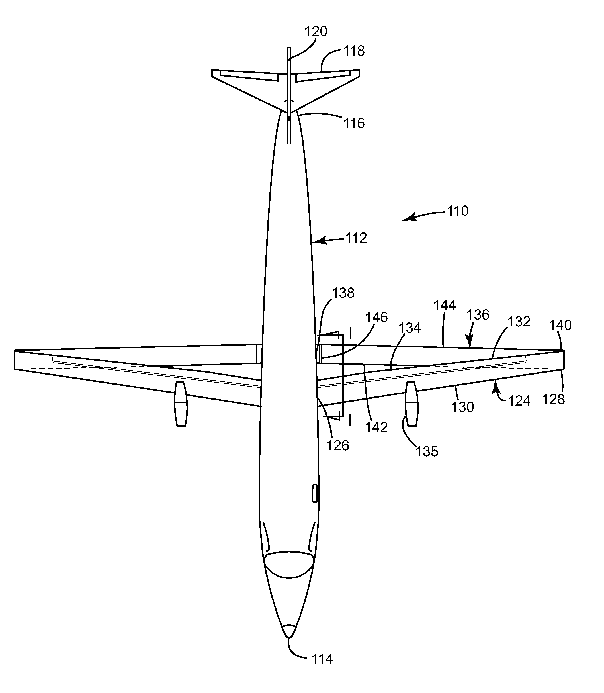
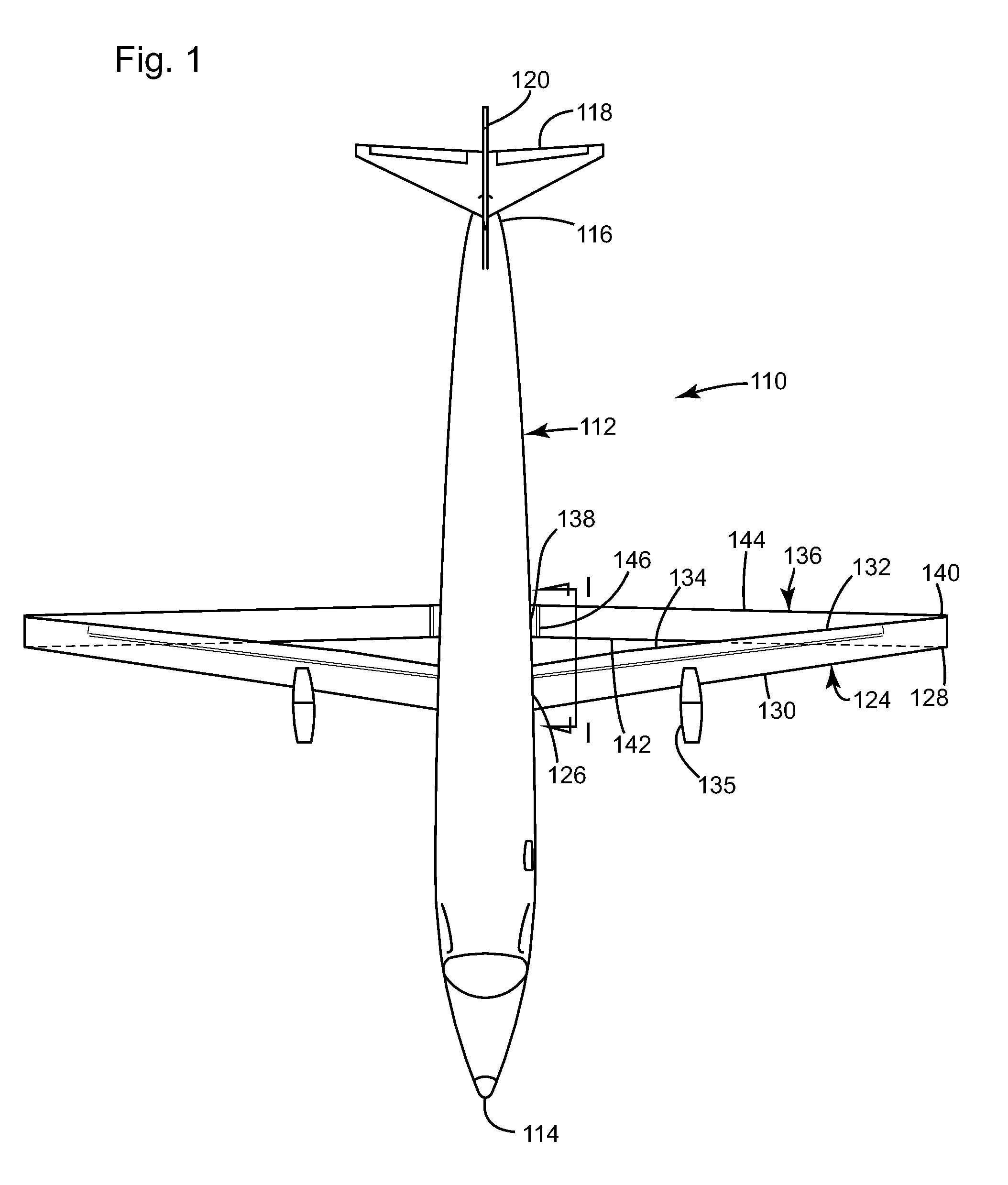
[0005]The present invention provides an improved airplane wing configuration including a dual wing arrangement. The present airplane wing configuration allows for substantially reduced landing speeds, making air travel safer, and thus for the use of shorter runways. The configuration greatly expands the airspeed envelope in which an airplane equipped with the present wing configuration is able to operate over previous wing configurations, and still allows the aircraft to maintain acceptable / comparable cruise efficiency and general fuel efficiency during normal operations.
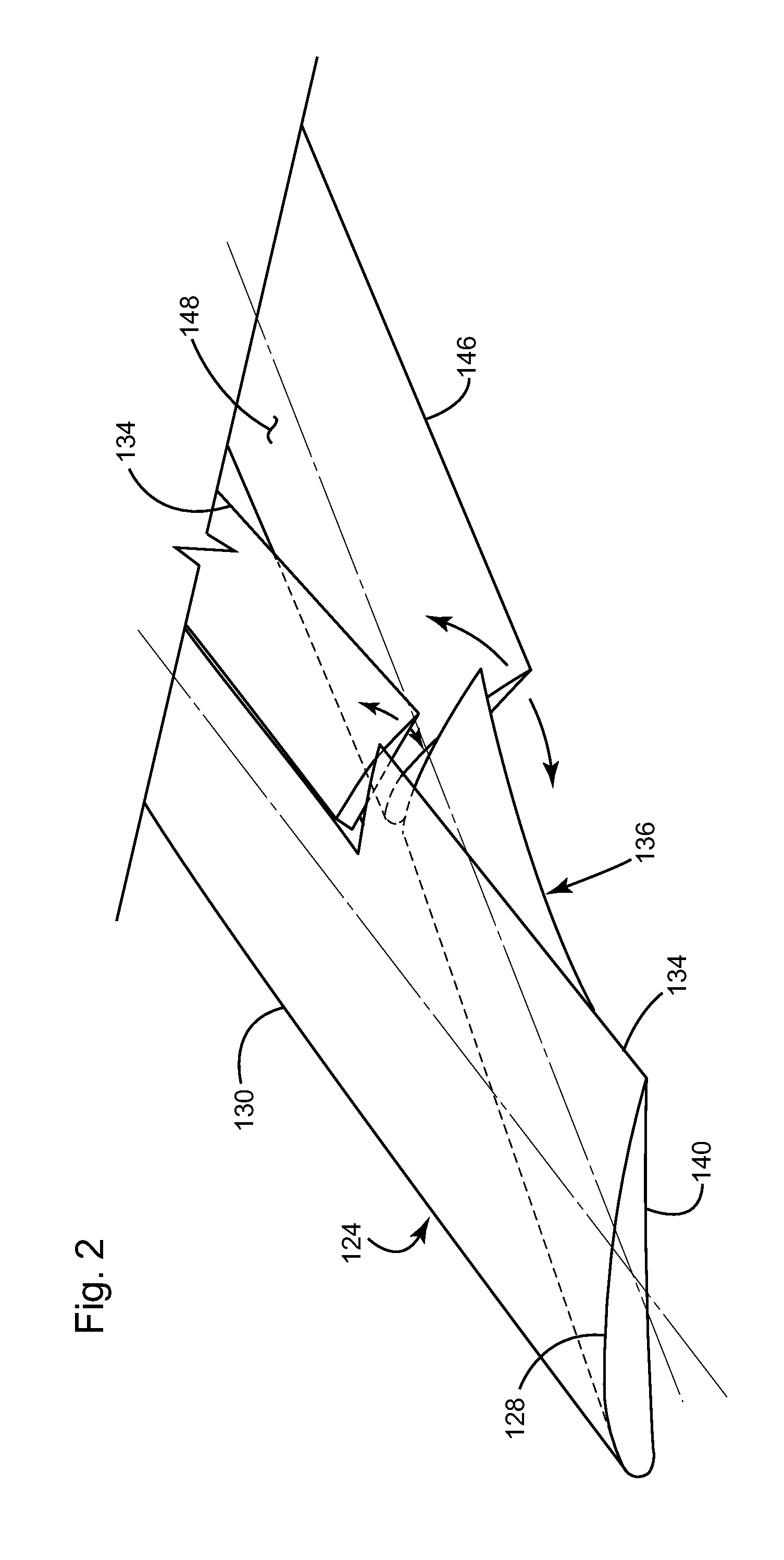
[0011]A method of configuring two airplane wings to act in concert with each other includes the steps of: fastening a first wing to an airplane fuselage, the first wing including a wing flap disposed at a trailing edge thereof; fastening a second wing to the airplane fuselage, the first wing being positioned above and forward of the second wing, and the second wing being operable to change its angle of attack independent of the first wing; adjusting the wing flap of the first wing to direct airflow from the first wing over an upper surface of the second wing; and rotating at least a portion of the second wing to increase the angle of attack of the second wing.

Problems solved by technology

While a biplane can produce more lift than a similarly sized monoplane of similar wingspan, the biplane produces more drag.
However, these conventional landing air speeds are by nature more dangerous than lower air speeds.
Also, the higher the landing air speed, the greater the wear on the airplanes tires due to increased friction on landing.

Method used


Image

  • Airplane wing
  • Airplane wing
  • Airplane wing

Examples


Embodiment Construction

[0038]The following glossary of definitions of terms used herein is provided for reference.

Angle of attack: The angle between a reference line on an airplane (such as the chord line of the airplane's wing) and the vector representing the relative motion between the airplane and the atmosphere through which it is moving.

Angle of incidence: The angle between the chord line of a wing and the longitudinal axis of the airplane fuselage.

Aspect ratio: Generally the ratio of the length of a wing to the width (chord) of the wing. A high aspect ratio refers to a long and slender wing.

Coanda effect: The tendency of a fluid jet to be attracted to a nearby surface and remains attached even when the surface curves away from the initial jet direction.

Chord: A line joining the trailing edge of a wing to the center of curvature of the leading edge of a cross-section of the wing.

Chord length: The distance between the trailing edge and the point on the leading edge where the chord intersects the leadi...


PUM

PropertyMeasurementUnit
Angleaaaaaaaaaa
Angleaaaaaaaaaa
Angleaaaaaaaaaa

Abstract

An airplane wing configuration includes a first wing positioned above and forward of a second wing on an airplane fuselage. The first wing is operable to direct airflow over an upper surface of the second wing, whereby the first and second wings are capable of generating greater lift than a sum of their individual lifts. The first wing may include an adjustable wing flap that redirects airflow over the upper surface of the second wing, and the second wing may include a rotatable portion that pivots to vary the angle of attack of the second wing independent of the first wing.

Description

CROSS-REFERENCE TO RELATED APPLICATIONS[0001]This application claims the priority of U.S. Provisional Application No. 61 / 385,987 filed Sep. 24, 2010 and U.S. Provisional Application No. 61 / 510,678 filed Jul. 22, 2011.TECHNICAL FIELD[0002]This invention relates to airplane wings, and more particularly to a dual wing configuration.BACKGROUND OF THE INVENTION[0003]It is known in the art relating to aircraft that modern, conventional airplanes typically are monoplanes that include one wing on each side of the fuselage. Another conventional wing configuration is a biplane in which the aircraft includes two wings stacked one on top of the other. While a biplane can produce more lift than a similarly sized monoplane of similar wingspan, the biplane produces more drag. Therefore, monoplanes have commonly been favored over biplanes.[0004]It is also known that conventional airplanes require a certain minimum air speed during landing in order to maintain lift. However, these conventional landi...

Claims


Application Information

Patent Timeline
IPC IPC(8): B64C39/12B64C3/48B23P11/00B64C3/50
CPCB64C3/385B64C9/12B64C39/04B64C39/068Y10T29/49826B64D27/06B64D27/18Y02T50/145Y02T50/32B64C39/08Y02T50/10Y02T50/30
Inventor HEATON, CLIFFORD D.
Owner HEATON CLIFFORD D
Learn More