Tubular beam with single center leg

a tubular beam and center leg technology, applied in bumpers, soldering devices, auxillary welding devices, etc., can solve the problems of increased capital investment, increased vehicle weight, and high tooling wear and tear

Inactive Publication Date: 2012-03-29
SHAPE CORP
View PDF13 Cites 36 Cited by
  • Summary
  • Abstract
  • Description
  • Claims
  • Application Information

AI Technical Summary

Benefits of technology

[0005]In one aspect of the present invention, a reinforcement beam includes a beam formed from a single sheet and including first and second tubes sharing a common wall and having coplanar aligned front walls and coplanar aligned rear walls, each front wall including a channel rib therein, the sheet including a first edge with a first radiused portion and first tip, a second edge with a second radiused portion and second tip, a third radiused portion connecting one of the aligned front walls with one end of the common wall, and a fourth radiused portion connecting one of the rear walls with another end of the common wall, the first and third radiused portions being welded together at a first weld and forming a front crevice rib having a cavity depth at least two times a thickness of the sheet, and the second and fourth radiused portions being welded together at a second weld and forming a rear crevice having a cavity depth at least two times the thickness of the sheet, the channel ribs and the front crevice rib forming ribs that stiffen a front face of the beam.

Problems solved by technology

Further, many of the desired features above are conflicting, such that it is not clear how to improve a particular bumper reinforcement beam, or how to improve the roll forming process for making the beam.
For example, a heavier beam may be stronger, but would cause an unacceptable increase in vehicle weight.
High strength materials may be preferred, but they are expensive, difficult to form, and cause high wear on tooling.
However, this can require extra roll forming steps and stations as well as additional tooling, hardware and software controls, each of which increase capital investment and make the roll forming process more complex.
However, welders take up space along the roll form apparatus, especially where the welders are positioned at different stations along a length of a roll form apparatus, thus increasing floor space requirements considerably, as well as capital investment.
Nonetheless, it is difficult to weld in two opposing sides of a beam due to flying debris adversely affecting one or both of the welders.

Method used


Image

  • Tubular beam with single center leg
  • Tubular beam with single center leg
  • Tubular beam with single center leg

Examples


Embodiment Construction

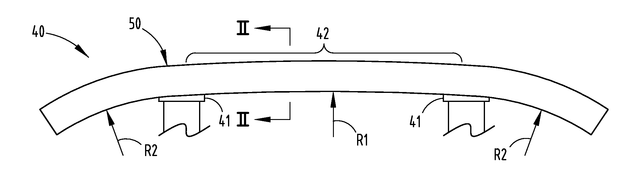
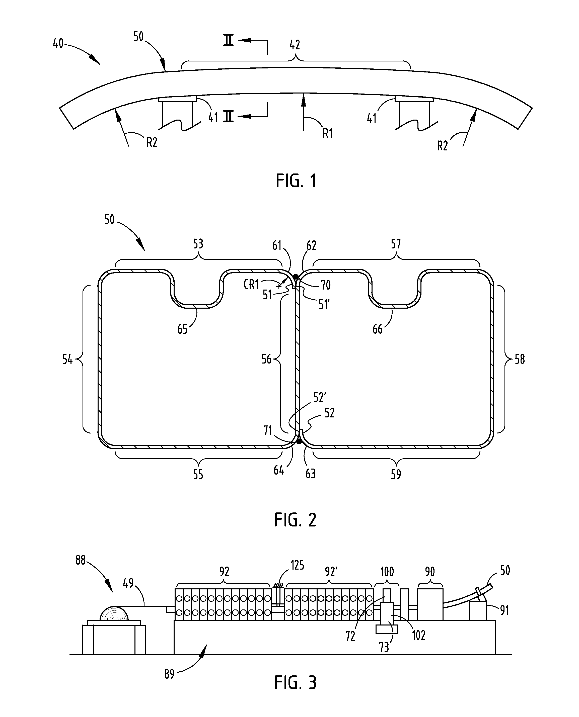
[0022]A bumper reinforcement beam 40 (FIG. 1) includes a tubular reinforcement beam 50 for a vehicle bumper system, and mounts 41 attached to the beam 50 to facilitate attachment to a vehicle frame, such as for use in a front bumper system (illustrated in FIG. 1) or rear bumper system of a vehicle. The illustrated beam 50 includes a longitudinal center section 42 curved at a first radius R1 and longitudinal outer ends curved at a tighter second radius R2 in order to match an aerodynamic shape of a particular vehicle. However, it is contemplated that the present inventive concepts can be used on any beam, whether linear or swept, and whether consistently curved / swept with a single radius or having different longitudinally-curves (“sweeps”).

[0023]The present beam 50 is made of sheet steel material having a thickness of 0.8 mm to 1.4 mm and a tensile strength of about 800 to 2000 MPa (i.e. about 120 to 290 ksi). The illustrated beam is about 80 mm high and 40 mm deep (in vehicle-mounte...


PUM

PropertyMeasurementUnit
thicknessaaaaaaaaaa
tensile strengthaaaaaaaaaa

Abstract

A reinforcement beam for a vehicle bumper system comprises a single sheet deformed to define first and second tubes sharing a common single center wall. A channel rib is formed on each tubes and a crevice rib over the center leg forms a third rib. Edges of the sheet are deformed to a radius so that their surface consistently engages an associated radiused corner formed on ends of the center leg, which facilitates consistent abutting line engagement of material surfaces, and thus facilitates consistent welding. In a preferred beam, front wall sections of each tube are coplanar and form a face of the beam, with each channel rib and crevice rib providing added stiffness to the beam, and yet nothing extends forward of the coplanar front wall sections. Related apparatus and methods are also disclosed.

Description

[0001]This application claims benefit under 35 USC section 119(e) of provisional application Ser. No. 61 / 385,680, filed Sep. 23, 2010, entitled TUBULAR BEAM WITH SINGLE CENTER LEG, the entire contents of which are incorporated herein by reference.BACKGROUND[0002]The present invention relates to bumper reinforcement beams used in vehicle bumper systems, where the beam is tubular and has a single (mono) center leg. The present invention also relates to roll forming apparatus and methods of forming said beams. However, the present invention is not believed to be limited to only bumper reinforcement beams for vehicles.[0003]Modern vehicle bumper systems typically include a reinforcement beam designed for strength and impact characteristics in order to meet government and insurance industry standards for particular vehicles, but also designed to minimize overall vehicle weight, to maximize strength-to-weight ratios, to fit within confined vehicle package spaces, and to satisfy vehicle ae...

Claims


Application Information

Patent Timeline
Patent Type & Authority Applications(United States)
IPC IPC(8): B60R19/02B21D5/12
CPCB21D5/086B23K2203/04B60R19/18B60R2019/1813B23K26/24B21D5/14B21D51/16B23K26/20B60R19/023B23K37/0235B23K37/0435B23K26/0621B23K26/0846B23K26/243B23K26/3206B23K2201/006B23K2201/18B21D53/88B23P23/00B23P2700/50B23K26/32B23K26/0619B23K26/242B23K2101/006B23K2101/18B23K2103/04B23K2103/50B60R2019/1826
Inventor JOHNSON, THOMASWITTE, DOUGGATTI, DANIELOXLEY, BRIANMALKOWSKI, BRIANRAMAMOORTHY, KANNANPENDERGRASS, ED
Owner SHAPE CORP
Why Eureka
Try Eureka