Estimation of loudspeaker positions

a loudspeaker position and position technology, applied in the direction of direction finders, loudspeaker enclosure positioning, instruments, etc., can solve the problems of increasing complexity and variation of sound systems, affecting the practicality of use, and the manual setting of individual parameters is quite cumbersome and impractical for the typical user, so as to achieve low cost and low cost. , the effect of low cos

Inactive Publication Date: 2012-03-29
KONINKLIJKE PHILIPS ELECTRONICS NV
View PDF28 Cites 28 Cited by
  • Summary
  • Abstract
  • Description
  • Claims
  • Application Information

AI Technical Summary

Benefits of technology

[0019]The approach may in many scenarios provide an improved direct assessment of the relative positions of speakers for a given listening position and does not rely on more complex, inaccurate, or error prone estimation indirect algorithms such as e.g. triangularization or least-squares estimation algorithms. Furthermore, the approach does not necessitate an...

Problems solved by technology

Sound systems are becoming increasingly advanced, complex and varied.
However, the ideal speaker position setup is often not replicated in practice due to the constraints of practical application environments.
For example, in a typical living room, it is often not possible or desired (e.g. for aesthetic reasons) to position a high number of loudspeakers at the positions which result in optimal performance.
However, such manual setting of individual parameters tends to be quite cumbersome and impractical for the typical user.
Furthermore, it tends to not provide optimal performance as the parameters that can be set are relatively limited (while still being confusing to many non-experts).
However, although such a process may improve the audio quality it provides relatively limited flexibility as the optimization is only based on the information provided by the microphone, and as such is limited to one listening position and to adaptation of parameters that affect the sound captured by the microphone.
For example, it does not provide any direct spatial information that can be used to optimize the system.
However, such an approach has some associated disadvantages.
For example, it requires additional hardware (a microphone) for each loudspeaker thereby inc...

Method used


Image

  • Estimation of loudspeaker positions
  • Estimation of loudspeaker positions
  • Estimation of loudspeaker positions

Examples


Embodiment Construction

[0061]The following description focuses on embodiments of the invention applicable to speaker position estimation in a home cinema surround sound system. However, it will be appreciated that the invention is not limited to this application but may be applied to speaker position estimation in many other sound systems.

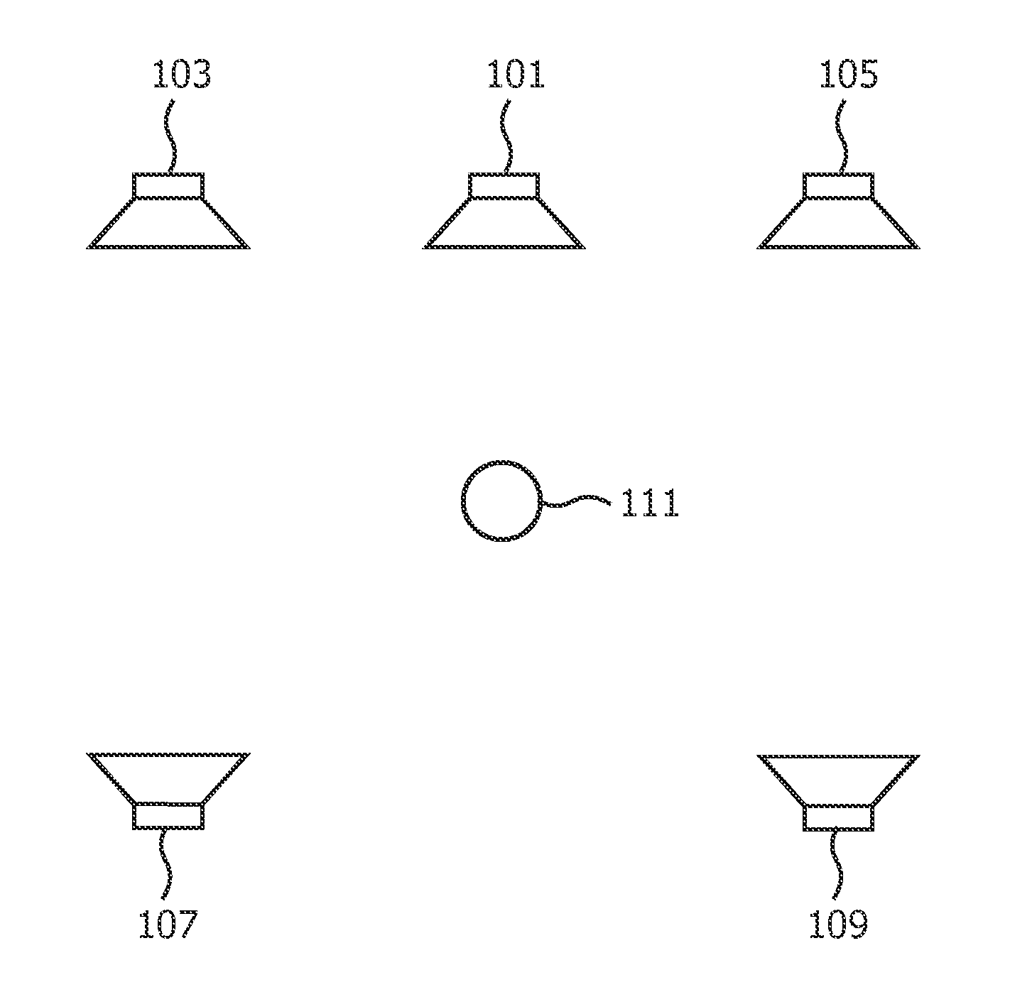
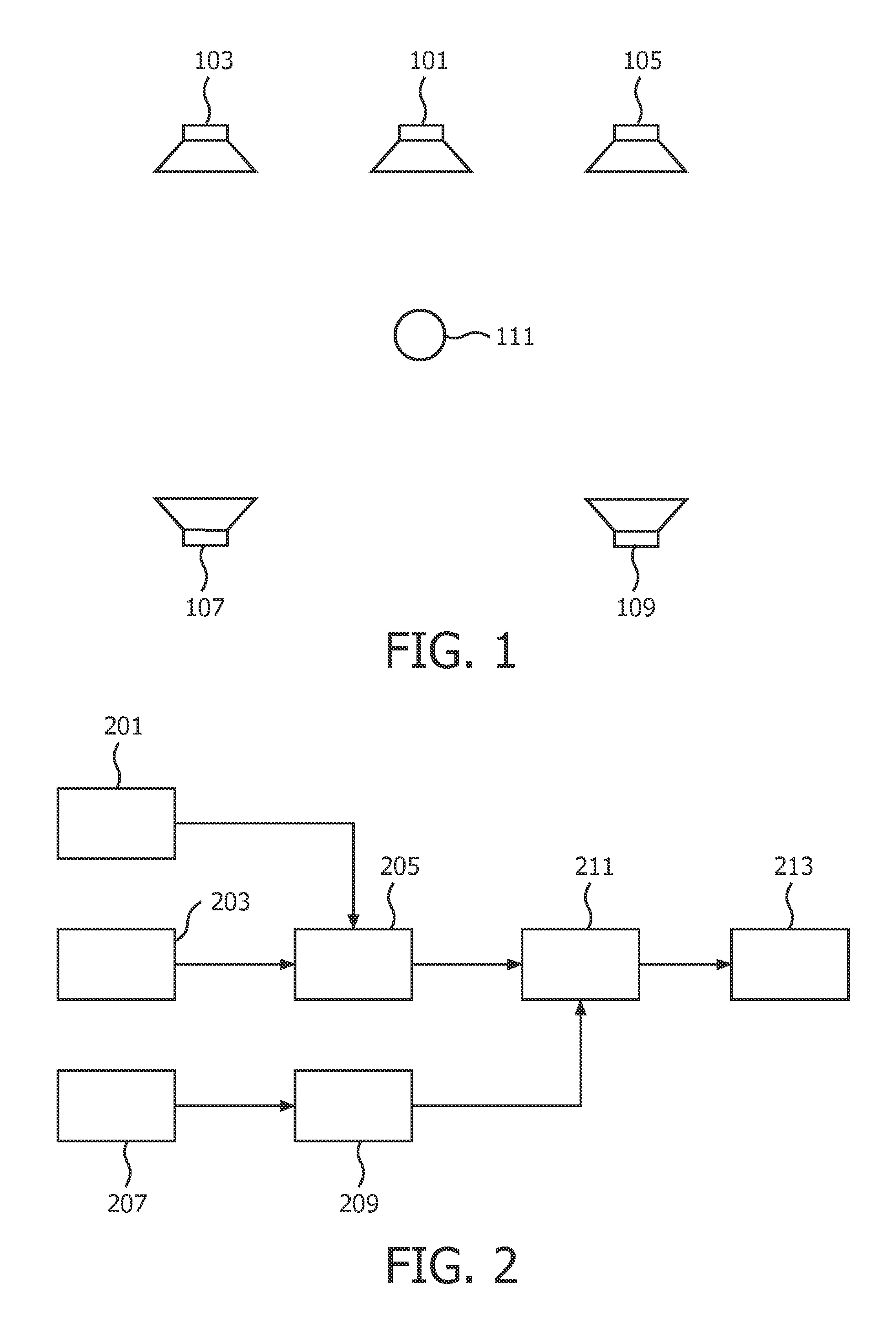
[0062]FIG. 1 illustrates a speaker system setup in a conventional five channel surround sound system, such as a home cinema system. The system comprises a center speaker 101 providing a center front channel, a left front speaker 103 providing a left front channel, a right front speaker 105 providing a right front channel, a left rear speaker 107 providing a left rear channel, a right rear speaker 109 providing a right rear channel. The five speakers 101-109 together provide a spatial sound experience at a listening position 111 and allow a listener at this location to experience a surrounding and immersive sound experience. In many home cinema systems, the system further...


PUM


Abstract

A system for determining loudspeaker position estimates comprises motion sensors (201, 203, 205) arranged to determine motion data for a user movable unit where the motion data characterizes movement of the user moveable unit. A user input (207, 209) receives user activations which indicate that at least one of a current position and orientation of the user movable unit is associated with a loudspeaker position when the user activation is received. The user activation may for example result from a user pressing a button. An analyzing processor (211) then generates loudspeaker position estimates in response to the motion data and the user activations. The system may e.g. allow a speaker position estimation to be based on a handheld device, such as a remote control, being pointed towards or positioned on a speaker.

Description

FIELD OF THE INVENTION[0001]The invention relates to estimation of loudspeaker positions and in particular, but not exclusively to estimation of loudspeaker positions in consumer surround sound systems.BACKGROUND OF THE INVENTION[0002]Sound systems are becoming increasingly advanced, complex and varied. For example, multi-channel spatial audio systems, such as five or seven channel home cinema systems, are becoming prevalent. However, the sound quality, and in particular the spatial user experience, in such systems is dependent on the relationship between the listening position and the loudspeaker positions. In many systems, the sound reproduction is based on an assumed relative speaker location and the systems are typically designed to provide a high quality spatial experience in a relatively small area known as the sweet spot. Thus, the systems typically assume that the speakers are located such that they provide a sweet spot at a specific nominal listening position.[0003]However,...

Claims


Application Information

Patent Timeline
IPC IPC(8): G01S3/00
CPCH04R2205/024H04S7/302H04S7/301
Inventor DE BRUIJN, WERNER PAULUS JOSEPHUS
Owner KONINKLIJKE PHILIPS ELECTRONICS NV
Why Eureka
Try Eureka