Laser amplification system

a technology of amplification system and laser, which is applied in the field of laser systems, can solve the problems of chirp pulse amplification, which requires an expensive set of opts, and achieve the effects of less expensive, less sensitive to air turbulence, and less expensiv

Active Publication Date: 2012-03-29
BOARD OF TRUSTEES OPERATING MICHIGAN STATE UNIV
View PDF2 Cites 16 Cited by
  • Summary
  • Abstract
  • Description
  • Claims
  • Application Information

AI Technical Summary

Benefits of technology

[0017]Referring to FIG. 2, a second embodiment laser amplification system 41 is set up in a multi-pass manner. An oscillator 43 emits a series of high peak intensity and ultrafast laser pulses 45 in a first direction transmitting through a pulse shaper optical member 47 and through an amplifier 49. The pulse is then reflected by a mirrored optic member 51. Thereafter, pulse 45 reverses direction and travels back along essentially the same path through amplifier 49 and through the same pulse shaper 47. A mirror 53 picks off the reversed and amplified pulse 45, and redirects it toward its target. This multi-task configuration provides a much less expensive and smaller sized system than with the first embodiment, and use of the same pulse shaper before and after amplification further ensures identical deconstructing and reconstructing phase functions, thereby improving accuracy. It is noteworthy that for both embodiment systems 21 and 41, the laser pulses 25 and 45 do not use chirped pulse amplification, and no stretcher or compressor is necessary in these system embodiments, yet the high peak intensity pulses will not damage the optics within the amplifier due to the present pulse shaping of the pulse.
[0029]The present laser amplification system is advantageous for communications uses over prior constructions since the present system obtains synergistic and multi-functional benefits of using the same pulse shaping optics to achieve many functions in a simultaneous manner. The present system advantageously transmits intense laser pulses through optical fibers, whether for communication or even portable medical uses, without harmfully causing extreme pulse broadening and power reduction, and possible destruction of the optical fiber. In other words, the present system suppresses and removes harmful self-phase modulation and other nonlinear optical processes while also eliminating self-focusing but with minimal phase manipulation. It should be appreciated that some form of chirping may slightly occur with the present amplification system, but such is not due to an unnecessary stretcher or traditional compressor.

Problems solved by technology

in. Chirp pulse amplification, however, requires an expensive set of opt

Method used


Image

  • Laser amplification system
  • Laser amplification system
  • Laser amplification system

Examples


Embodiment Construction

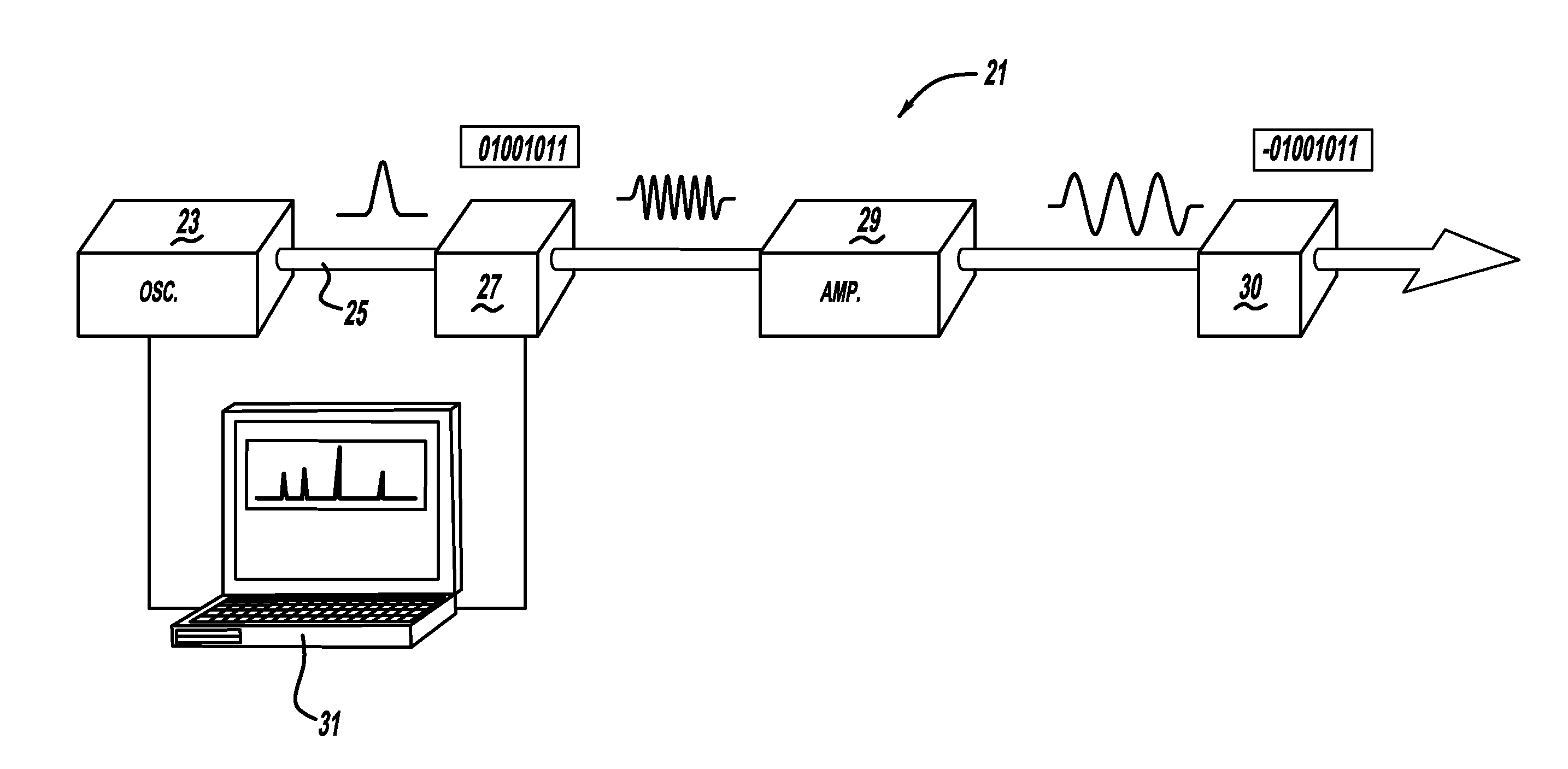
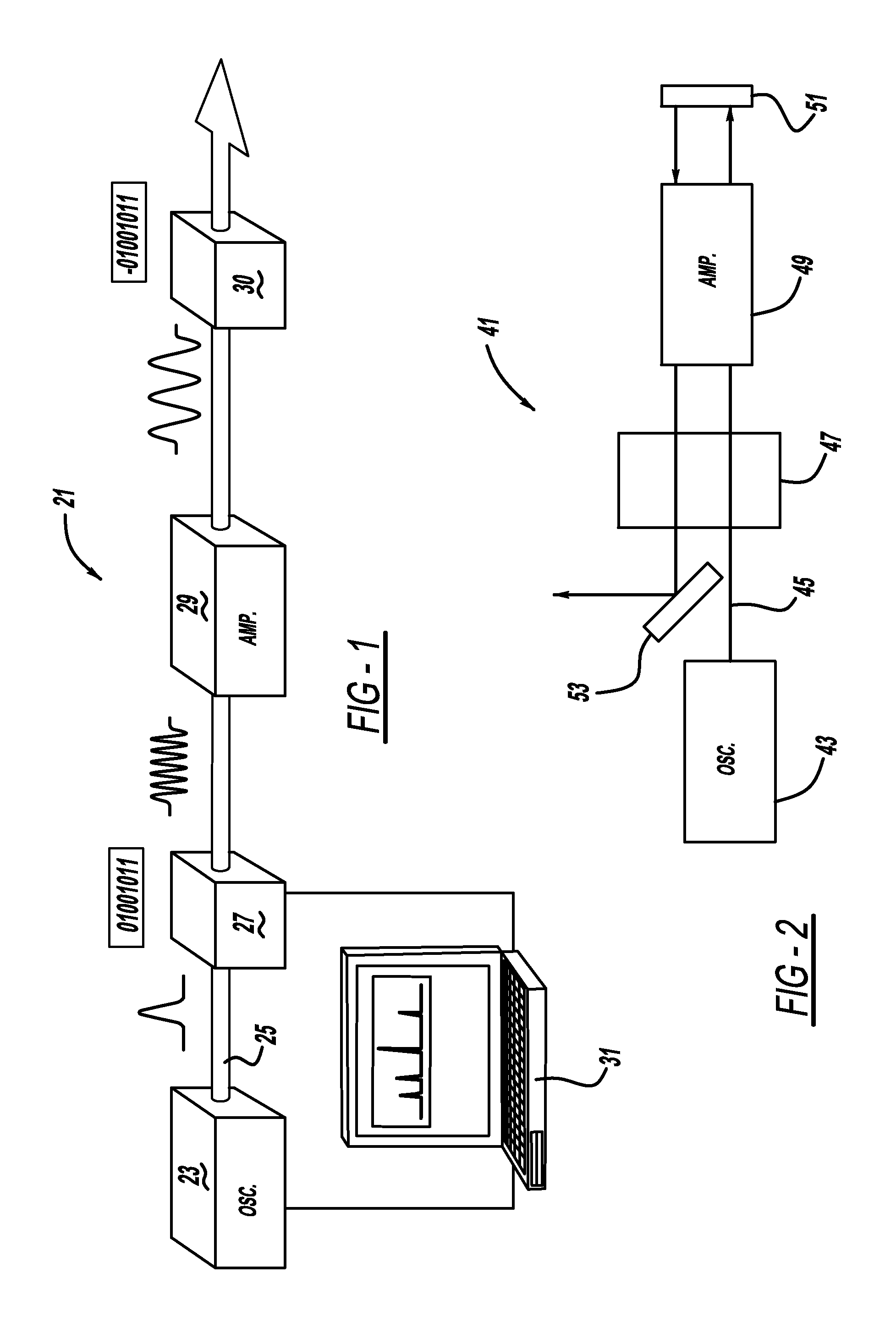
[0015]The first embodiment of a laser amplification system 21 is shown in FIG. 1. A Ti:Sapphire laser oscillator 23 emits a series of high peak intensity laser beam pulses 25 through a pulse shaper 27, to an amplifier 29 and through a second pulse shaper 30. A satisfactory oscillator can be obtained from KM Labs, and has an 86 mhz repetition rate at ˜100 nm FWHM bandwidth. A satisfactory amplifier can be obtained from Coherent Inc., namely the Legend USP Model which generates pulses at or less than 35 femtoseconds at 800 nm. The high peak intensity laser pulse has a typical peak intensity greater than about 1 kW and each laser pulse preferably has a duration of less than 100 picoseconds, more preferably less than 10 picoseconds, and even more preferably equal to or less than 25 femtoseconds. Alternately, a fiber oscillator followed by a fiber amplifier can be employed.

[0016]A computer controller 31 is electrically connected to control oscillator 23 and at least one of the pulse shap...


PUM


Abstract

A high peak intensity laser amplification system and the method therein implemented are provided. In a first aspect of the invention, the laser system includes at least one optical member (27) operably introducing a phase function into a high peak intensity laser pulse (25). A further aspect includes introducing destructive interference in an unchirped laser pulse prior to amplification and reconstructive interference in the output laser pulse after amplification. Dynamic pulse shaping is employed in another aspect of the present invention.

Description

CROSS-REFERENCE TO RELATED APPLICATIONS[0001]This application claims the benefit and priority of U.S. Provisional Application No. 61 / 157,718, filed on Mar. 5, 2009, which is incorporated by reference herein.BACKGROUND AND SUMMARY[0002]The present invention generally relates to laser systems and more particularly to a laser amplification system.[0003]It is known to employ chirp pulse amplification (“CPA”) for ultrashort lasers. Chirping overcomes concerns with intense ultrashort laser pulses inducing nonlinear optical processes in transparent media which would otherwise damage the amplification equipment. When chirp pulse amplification is used, the pulses are stretched by a factor greater than 1000 and therefore their intensity is significantly reduced. Examples of chirp pulse amplification can be observed in the following U.S. Pat. Nos. 5,862,287 entitled “Apparatus And Method For Delivery Of Dispersion Compensated Ultrashort Optical Pulses With High Peak Power” which issued to Stoc...

Claims


Application Information

Patent Timeline
Patent Type & Authority Applications(United States)
IPC IPC(8): H04B10/18H04B10/04H01S3/067H01S3/10H01S3/13
CPCH01S3/005H01S3/23H01S3/0057
Inventor DANTUS, MARCOSLOZOVOY, VADIM V.
Owner BOARD OF TRUSTEES OPERATING MICHIGAN STATE UNIV
Why Eureka
Try Eureka