Honeycomb structural body and electrical heated catalyst device

a technology of catalyst device and honeycomb structure, which is applied in the direction of machines/engines, mechanical equipment, separation processes, etc., can solve the problems of difficulty in increasing the temperature difficulty in allowing current to flow through a long distance between the electrode pair, and non-uniform temperature distribution in etc., to achieve uniform temperature of the inside of the honeycomb structure body, easy to mount, and high efficiency

Active Publication Date: 2012-03-29
DENSO CORP
View PDF4 Cites 58 Cited by
  • Summary
  • Abstract
  • Description
  • Claims
  • Application Information

AI Technical Summary

Benefits of technology

[0013]It is an object of the present invention to provide a honeycomb structural body and an electrically heated catalyst (EHC) device equipped with the honeycomb structural body which is capable of being easy to be mounted to an exhaust gas pipe of an exhaust gas purifying system, and of being increased uniformly to a desired temperature.

Problems solved by technology

This electrode structure causes a problem of it being difficult for the current to flow through a long distance between the electrode pair (for example, a distance at the central parts between the positive electrode and the negative electrode) when compared with the current flowing through a short distance at the end parts between the positive electrode and the negative electrode (for example, a distance at the outside portion between the positive electrode and the negative electrode).
This causes non-uniform temperature distribution in the inside of the honeycomb structural body because of causing unbalanced temperature distribution in the inside of the honeycomb structural body.
This structure causes a difficulty of increasing the temperature of the honeycomb structural body as soon as electrical power is supplied.
Further, this conventional honeycomb structural body has a possibility of decreasing the entire strength and the capability of purifying exhaust gas because of having the slit part in the honeycomb structural body.
H04-280086 has a square shape or a race-track shape, there is a possibility of it being difficult to mount it in an exhaust gas pipe of a motor vehicle.
That is, the structure of this conventional honeycomb structural body has a drawback on mounting it to the exhaust gas pipe in the exhaust gas purifying system for the internal combustion engine of a motor vehicle.

Method used


Image

  • Honeycomb structural body and electrical heated catalyst device
  • Honeycomb structural body and electrical heated catalyst device
  • Honeycomb structural body and electrical heated catalyst device

Examples


first exemplary embodiment

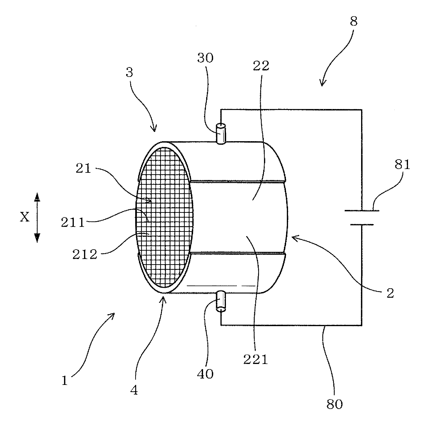
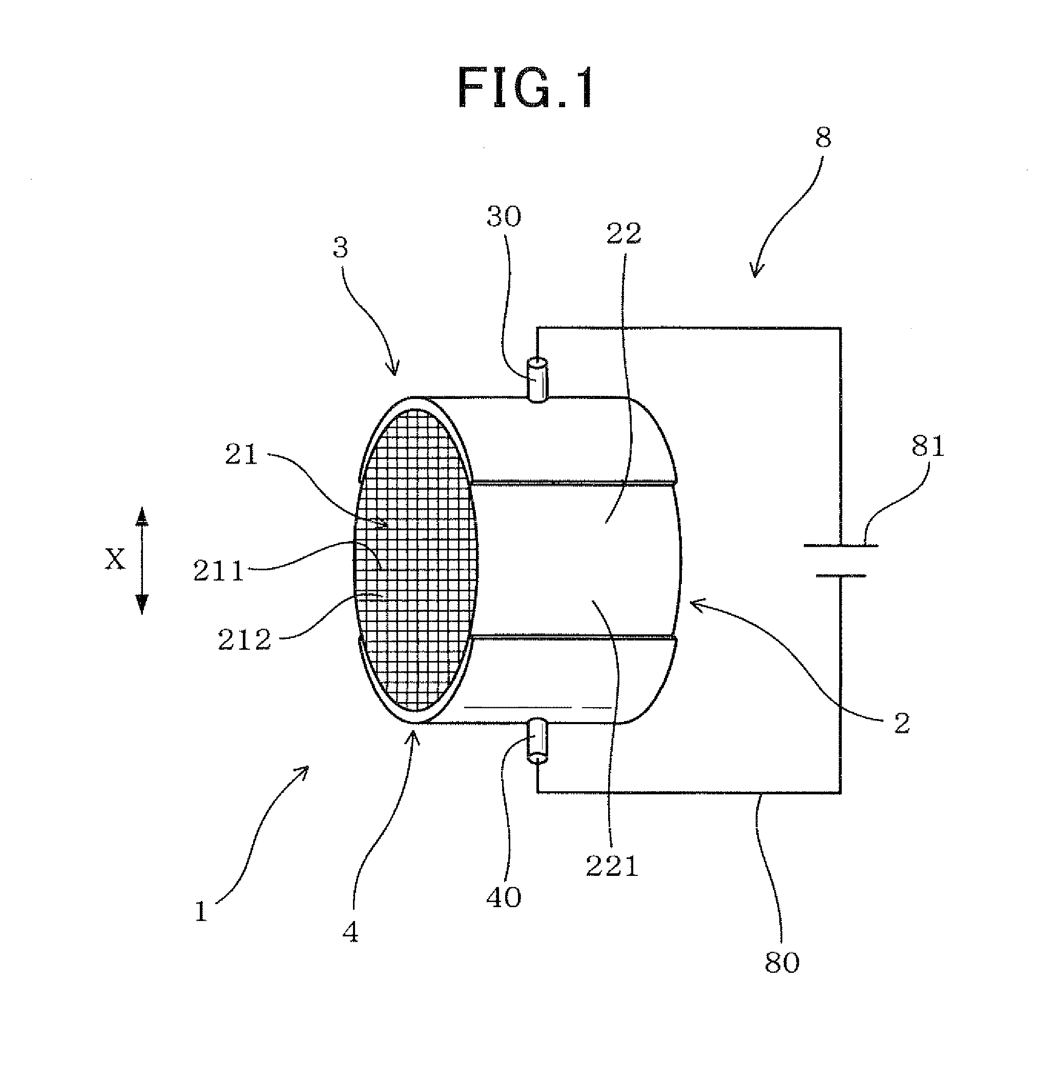
[0040]A description will be given of a honeycomb structural body and an electrically heated catalyst (EHC) device, as an electrical heating type, equipped with the honeycomb structural body according to a first exemplary embodiment of the present invention with reference to FIG. 1 and FIG. 2.

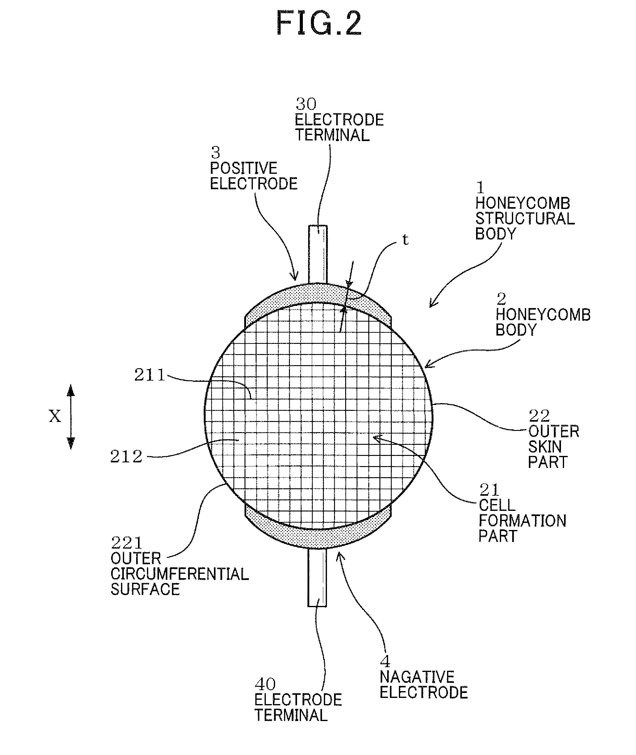
[0041]FIG. 1 is a view showing a perspective configuration of the honeycomb structural body 1 according to the first exemplary embodiment of the present invention. FIG. 2 is a view showing a cross section of the honeycomb structural body 1. The cross section shown in FIG. 2 is perpendicular to an axial direction of the honeycomb structural body 1.

[0042]As shown in FIG. 1 and FIG. 2, the honeycomb structural body 1 according to the first exemplary embodiment is comprised of a honeycomb body 2 and a pair of a positive electrode 3 and a negative electrode 4. The honeycomb body 2 has a cell formation part 21 and an outer skin part 22 of a cylindrical shape. The cell formation part 21 is covered with...

second exemplary embodiment

[0072]A description will be given of the honeycomb structural body 1-1 having the honeycomb body 2 and a positive electrode 3-1 and a negative electrode 4-1 with reference to FIG. 4.

[0073]Each of the positive electrode 3-1 and the negative electrode 4-1 has a different structure when compared with the structure of each of the positive electrode 3-1 and the negative electrode 4-1 shown in FIG. 1 and FIG. 2.

[0074]FIG. 4 is a view showing a cross section of the honeycomb structural body 1-1, which is perpendicular to an axial direction thereof, according to the second exemplary embodiment of the present invention.

[0075]As shown in FIG. 4, the positive electrode 3-1 is comprised of a reference electrode part 31 and outside electrode parts 32a and 32b. The reference electrode 31 is formed at a central part of the positive electrode 3 in the circumferential direction. The outside electrode parts 32a and 32b are arranged at both sides of the reference electrode part 31 in the circumferenti...

third exemplary embodiment

[0104]A description will be given of the honeycomb structural body 1-3 equipped with the positive electrode 3-3 and the negative electrode 4-3 having other structure according to the third exemplary embodiment with reference to FIG. 7 and FIG. 8.

[0105]FIG. 7 is a view showing a cross section of the honeycomb structural body 1-3, which is perpendicular to an axial direction thereof, according to the third exemplary embodiment of the present invention. FIG. 8 is a view showing an enlarged cross section of a part around the positive electrode 3-3 formed on the surface of the honeycomb body 2 in the honeycomb structural body 1-3 according to the third exemplary embodiment.

[0106]As shown in FIG. 7 and FIG. 8, in the positive electrode 3-3, gaps 50 are formed between the reference electrode part 31 and the outside electrode part 32a, and gaps 50 are formed between the reference electrode part 31 and the outside electrode part 32b. Similar to the positive electrode 3-3, in the negative ele...


PUM

PropertyMeasurementUnit
thicknessaaaaaaaaaa
thicknessaaaaaaaaaa
temperatureaaaaaaaaaa

Abstract

A honeycomb structural body has a honeycomb body and an electrode pair. The honeycomb body has a cell formation part and an outer skin part of a cylindrical-hollow shape. The electrodes are formed on an outer peripheral surface of the outer skin part so that the electrodes face to each other in a diameter direction of the honeycomb body. Each electrode has a reference electrode part formed at a central part of the electrode and one or more outside electrode parts formed at both ends of the reference electrode part. An electrode terminal is formed at the central part of each electrode. The reference electrode parts of the electrodes face to each other. The outside electrode parts of the electrodes face to each other. A thickness of each electrode is gradually decreased from the central part toward the outside of the electrode along the circumferential direction of the honeycomb body.

Description

CROSS-REFERENCE TO RELATED APPLICATION[0001]This application is related to and claims priority from Japanese Patent Applications No. 2010-215963 filed on Sep. 27, 2010, and No. 2011-120958 filed on May 30, 2011, the contents of which are hereby incorporated by reference.BACKGROUND OF THE INVENTION[0002]1. Field of the Invention[0003]The present invention relates to honeycomb structural bodies to be used for purifying exhaust gas emitted from an internal combustion engines, and electrically heated catalyst (EHC) devices equipped with the honeycomb structural body.[0004]2. Description of the Related Art[0005]In general, a catalyst device is mounted to an exhaust gas pipe of an exhaust gas purifying system through which exhaust gas emitted from an internal combustion engine of a motor vehicle flows and purified. The catalyst device is capable of purifying exhaust gas. In general, such a catalyst device uses a honeycomb structural body which supports catalyst such as platinum (Pt), pall...

Claims


Application Information

Patent Timeline
Patent Type & Authority Applications(United States)
IPC IPC(8): B01D53/94B01J8/00
CPCB01J19/2485B01J2219/2416F01N3/2026Y02T10/26H05B2203/016H05B2203/024H05B3/42Y02T10/12
Inventor ISHIHARA, MIKIO
Owner DENSO CORP
Why Eureka
Try Eureka