Method of anchoring autologous or artificial tendon grafts in bone

a technology of autologous or artificial tendon grafts and bone, applied in the field of surgical systems, can solve the problems of cruciate ligaments, difficult to harvest tendon, postoperative complications, etc., and achieve the effect of strong pressure fi

Inactive Publication Date: 2012-03-29
DEPUY MITEK INC
View PDF13 Cites 32 Cited by
  • Summary
  • Abstract
  • Description
  • Claims
  • Application Information

AI Technical Summary

Benefits of technology

[0015]According to one aspect of the invention, the stabilizing element has a threaded outer surface that can be securely turned into the bone. In addition, the stabilizing element can have an inner bore that is smaller than the outer diameter of the insertion element, such that placement of the latter into the former causes the stabilizing element to deformably expand or otherwise obtain a still stronger pressure fit with the bone hole.
[0016]In another aspect,

Problems solved by technology

Athletes, for example, often suffer tears or other injuries to the anterior cruciate ligament, one of the ligaments connecting the femur.
The ACL, which limits hyperextension of the knee and prevents the backward sliding of the femur on the tibial plateau, may be injured when the knee is twisted beyond the normal range of motion, e.g., when the knee is twisted while bending and weaving during skiing and other sports activities.
Drawbacks associated with the use of the patellar tendon-include difficulties in harvesting the tendon and postoperative complications.
Although semitendinosus tendons are increasingly used in ACL repair, they are difficult to attach to bone, due in part to the absence of asso

Method used


Image

  • Method of anchoring autologous or artificial tendon grafts in bone
  • Method of anchoring autologous or artificial tendon grafts in bone
  • Method of anchoring autologous or artificial tendon grafts in bone

Examples


Embodiment Construction

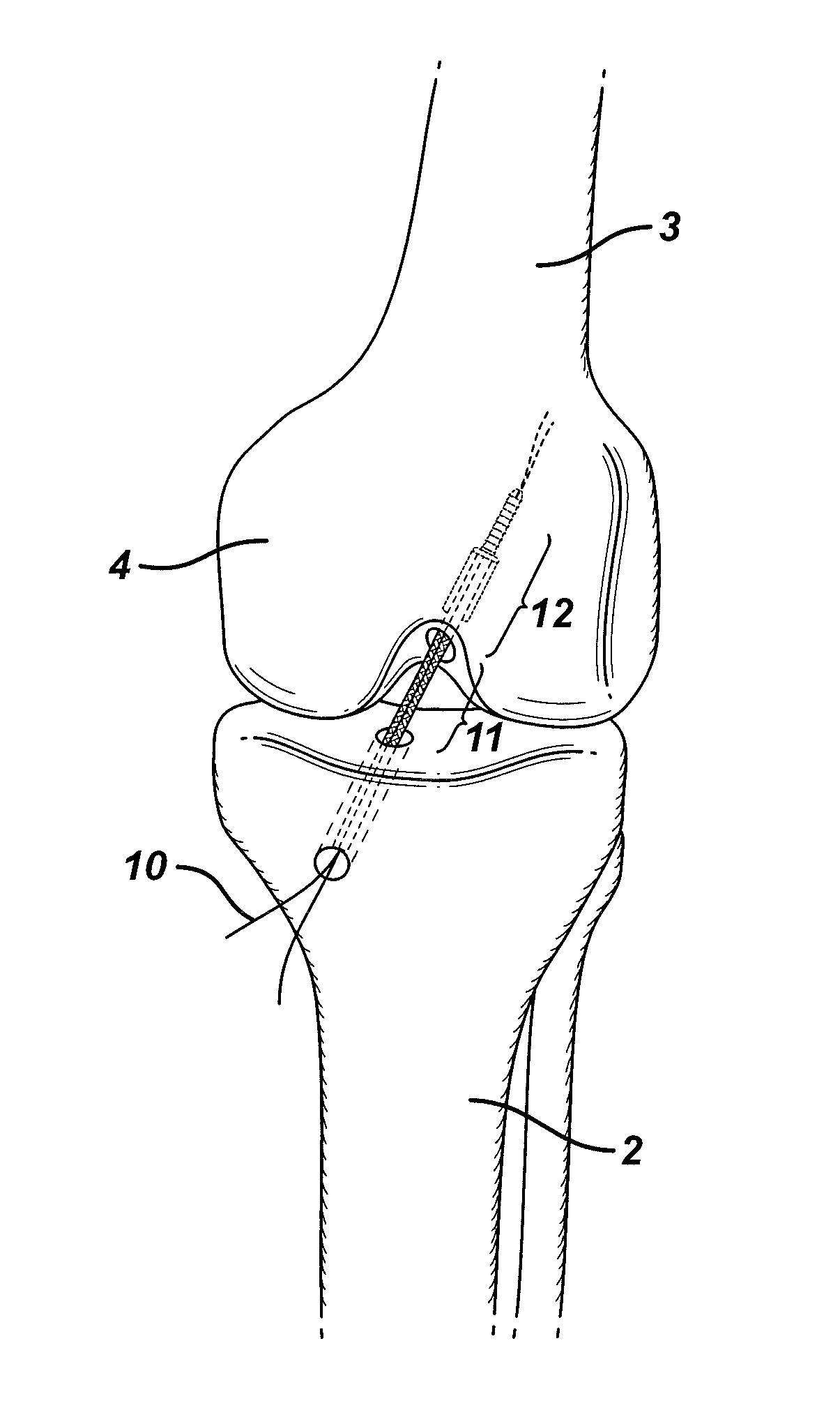
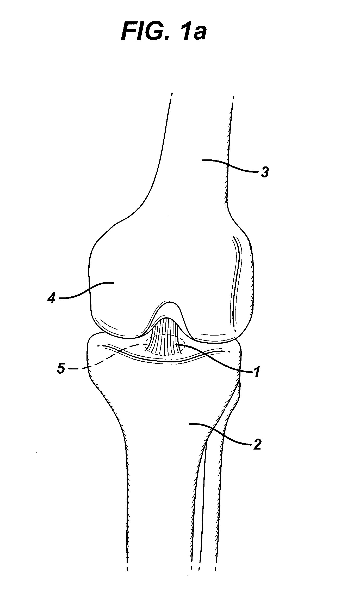
[0041]FIG. 1a depicts a partially torn ligament of the knee, e.g., the anterior cruciate ligament (ACL) 1. In the illustration, the ACL is attached to a depression in the anterior intercondylar area (not shown) on the surface of the tibial plateau 5. This tibial attachment lies in front of the anterior intercondylar tubercle and is blended with the anterior extremity of the lateral meniscus (not shown). It passes upward, backward, and laterally to be fixed into the posterior part of the medial surface of the lateral condyle (not shown) of the femur 3. The tibia 2 and the patella 4 are also shown.

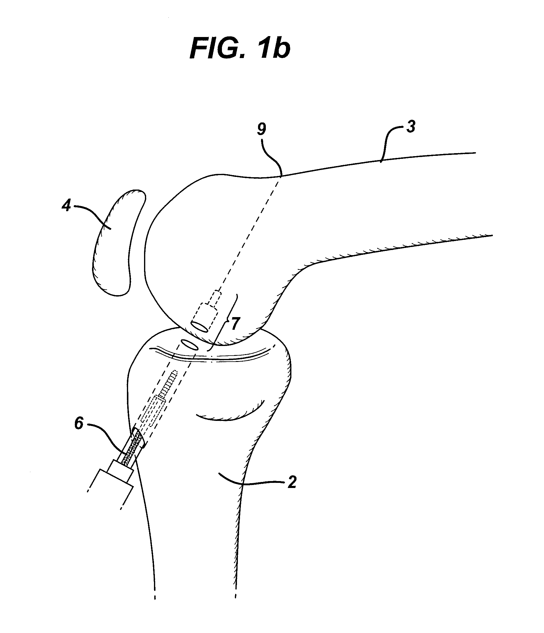
[0042]FIG. 1b depicts a method for creating a stepped tunnel 7 through the tibia 2 and partially through the femur 3 for insertion of an anchor assembly of the invention. In the illustration, a drill 6 is used by the surgeon to drill a tunnel beginning at the anterior surface of the tibia 2 and ending within the cancellous region of the femur 3. The drill tunnel 7 preferably will enter the f...


PUM


Abstract

An anchor assembly for autologous or artificial tendon grafts comprises an insertion element and a stabilizing element. The insertion element has a stem and a head containing an aperture large enough to receive a graft. The stabilizing element is adapted to be embedded in bone, and comprises a sleeve with a cavity arranged to receive and hold the insertion element stem. In use, the stabilizing element is affixed in the bone, and the stem of the insertion element is placed therein. A tendon graft may be secured to the insertion element either before or after its placement in the stabilizing element. Two such anchors may be linked with one or multiple grafts, in either a two-ply or four-ply arrangement.

Description

CROSS-REFERENCE TO RELATED APPLICATIONS[0001]This application is a divisional application of U.S. patent application Ser. No. 12 / 617,392 filed on Nov. 12, 2009, which is a divisional application of U.S. patent application Ser. No. 10 / 623,212 filed on Jul. 18, 2003, now U.S. Pat. No. 7,637,949, which is a divisional application of U.S. patent application Ser. No. 08 / 976,257 filed Nov. 21, 1997 (now U.S. Pat. No. 6,616,694), which is a continuation-in-part of both U.S. patent application Ser. No. 08 / 887,580, filed Jul. 3, 1997 now abandoned, and of U.S. patent application Ser. No. 08 / 754,566, filed Nov. 21, 1996 now abandoned, the contents of which are incorporated herein by reference in their entireties.BACKGROUND OF THE INVENTION[0002]This invention pertains to surgical systems and, more particularly, apparatus and methods for attaching autologous or artificial tendon grafts to bone. The invention has application in, for example, repair of the anterior cruciate ligament (ACL) of the...

Claims


Application Information

Patent Timeline
IPC IPC(8): A61F2/08A61B17/68
CPCA61B17/686A61F2/0811A61F2002/0882A61F2002/0852A61F2002/0835
Inventor HART, RICKEY D.
Owner DEPUY MITEK INC
Why Eureka
Try Eureka