Electronic analyte assaying device

an electrochemical and analyte technology, applied in the direction of instruments, chemical methods analysis, analysis using chemical indicators, etc., can solve the problem of troublesome false positives

Active Publication Date: 2012-04-05
CHURCH & DWIGHT CO INC
View PDF0 Cites 30 Cited by
  • Summary
  • Abstract
  • Description
  • Claims
  • Application Information

AI Technical Summary

Benefits of technology

[0021]In still other embodiments, the method further comprises the step of minimizing the effect of fluid channeling along the length of the test strip by providing pressure across the width of the test strip. In some of these embodiments, the pressure across the width of the test strip is provided by a light shield placed in contact with the test strip.
[0022]In another preferred embodiment of a diagnostic device for detecting the presence of an analyte in a fluid sample, the device comprises a casing having a display, a test strip mounted in the casing, the test strip having a length and a width and a test result site located thereon, a light shield mounted in the casing adjacent the test strip, the light shield having at least two through holes formed therein, a processor mounted in the casing, a sensor mounted in the casing adjacent one of the at least two through holes, the sensor being operatively coupled to the processor, and a light source mounted in the casing adjacent to the other of the at least two through holes, the light source being operatively coupled to the processor. A portion of the light shield is configured to exert pressure across the width of the test strip to prevent fluid channeling along the length of the test strip.

Problems solved by technology

False positives can be troublesome, particularly with agglutination and other rapid detection methods such as dipstick and color change tests.

Method used


Image

  • Electronic analyte assaying device
  • Electronic analyte assaying device
  • Electronic analyte assaying device

Examples


Embodiment Construction

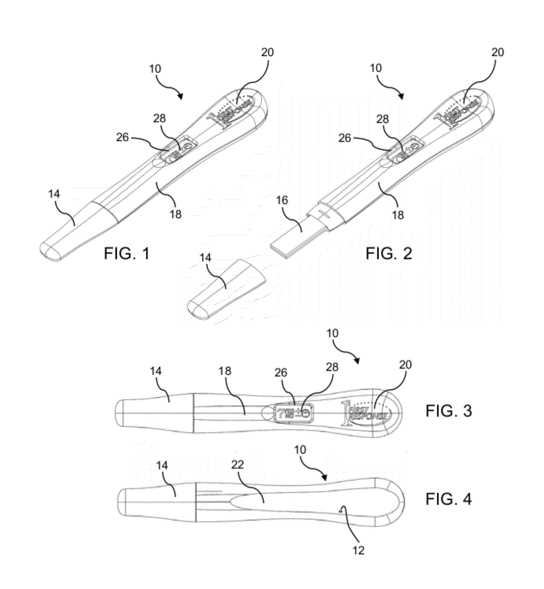
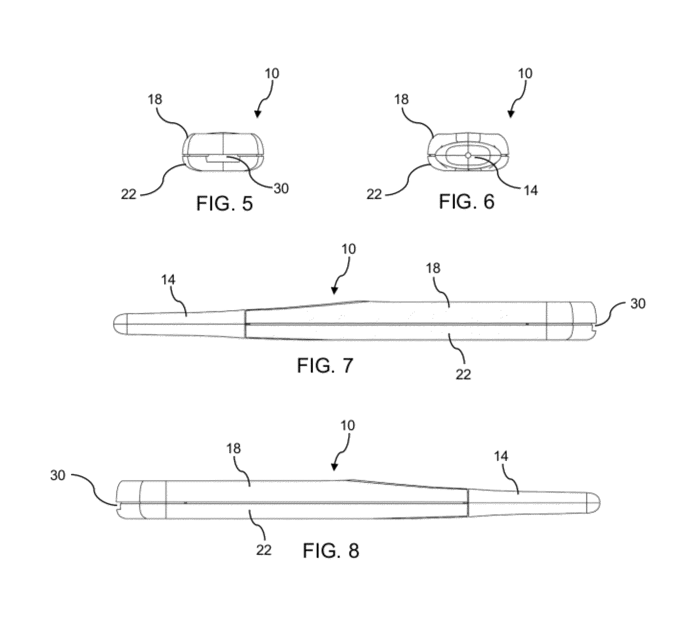
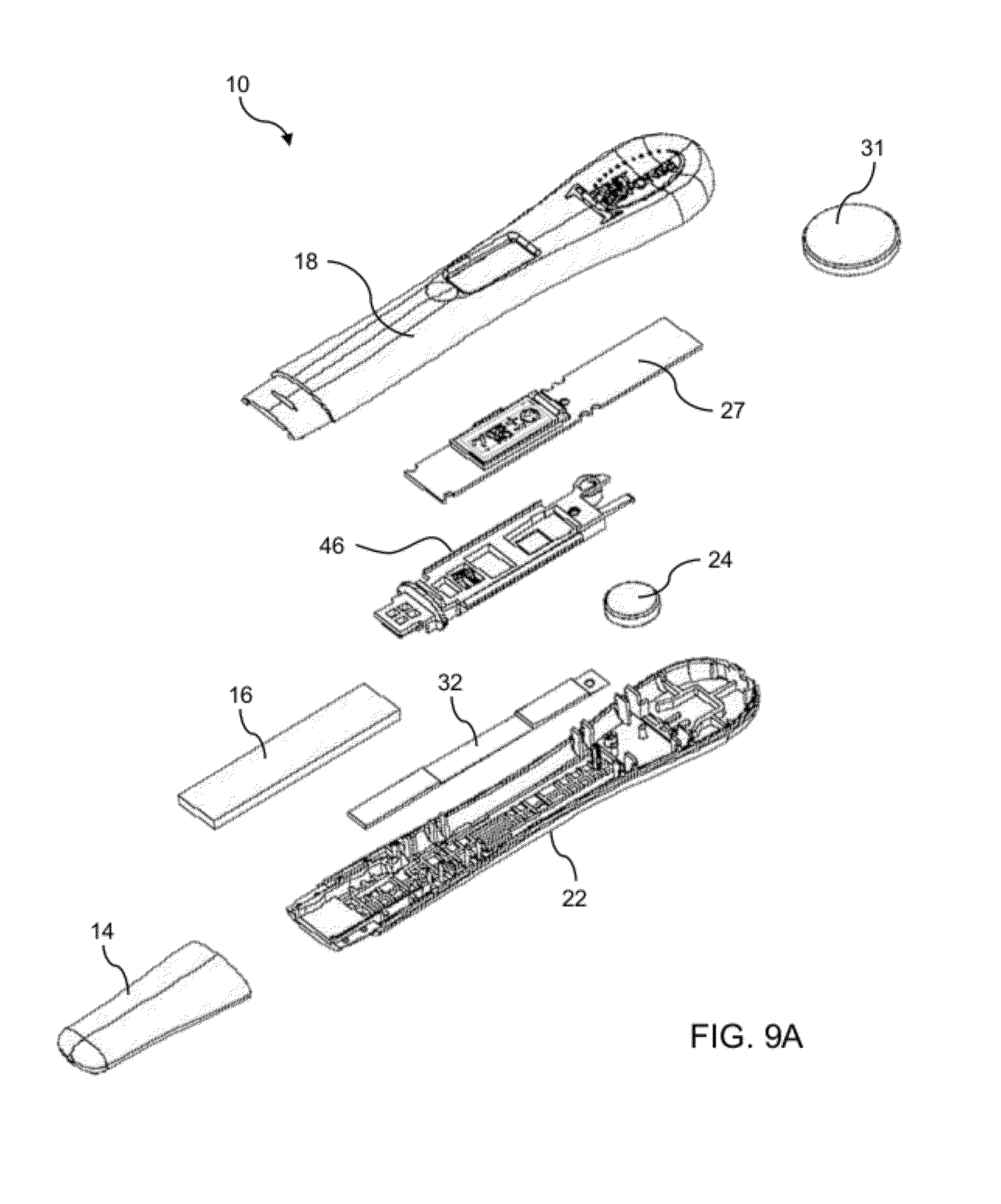
[0050]Reference will now be made in detail to presently preferred embodiments of the invention, one or more examples of which are illustrated in the accompanying drawings. Each example is provided by way of explanation, not limitation, of the invention. It is to be understood by one of ordinary skill in the art that the present discussion is a description of exemplary embodiments only, and is not intended as limiting the broader aspects of the present invention, which broader aspects are embodied in the exemplary constructions. In fact, it will be apparent to those skilled in the art that modifications and variations can be made in the present invention without departing from the scope and spirit thereof. For instance, features illustrated or described as part of one embodiment may be used on another embodiment to yield a still further embodiment. Thus, it is intended that the present invention covers such modifications and variations as come within the scope of the appended claims ...


PUM

PropertyMeasurementUnit
time periodaaaaaaaaaa
timeaaaaaaaaaa
areaaaaaaaaaaa

Abstract

An improved electronic diagnostic device for detecting the presence of an analyte in a fluid sample comprises a casing having a display, a test strip mounted in the casing, a processor mounted in the casing, and a first sensor mounted in the casing and operatively coupled to the processor. The processor is configured to receive a signal from the first sensor when the device is exposed to ambient light thereby causing the device to become activated. The device includes a light shield that exerts pressure across a width of the test strip to prevent fluid channeling along the length of the test strip. The processor is configured to present an early positive test result reading when a measured value exceeds a predetermined early reading threshold value at any time after a predetermined early testing time period.

Description

CLAIM OF PRIORITY[0001]This application claims priority to U.S. Provisional Application Ser. No. 61 / 389,050, filed on Oct. 1, 2010, the entire disclosure of which is incorporated by reference herein.FIELD OF THE INVENTION[0002]The invention relates to diagnostic assays for analytes in a liquid sample. In particular, the invention relates to an improved electronic device for detecting an analyte in a body fluid and a method of using the device for assay test results.BACKGROUND OF THE INVENTION[0003]Many types of ligand-receptor assays have been used to detect the presence of various substances in body fluids, such as urine, saliva, or blood. Many of these assays are designed to make a quantitative determination, but in many circumstances all that is required is a qualitative positive / negative indication. Examples of such qualitative assays include blood typing, pregnancy testing, and many types of urinalysis. For these tests, visually observable indicia, such as the presence of agglu...

Claims


Application Information

Patent Timeline
Patent Type & Authority Applications(United States)
IPC IPC(8): G01N21/75
CPCG01N21/8483G01N21/17G01N33/76G01N33/62G01N33/689G01N33/493G01N33/48792G01N33/48785G01N2201/062G01N2201/12G01N2333/59
Inventor STURMAN, ANDYZIN, BENEDICTNAZARETH, ALBERTBELL, HENRY
Owner CHURCH & DWIGHT CO INC
Why Eureka
Try Eureka