Operation Management Apparatus, Operation Management Method, and Operation Management Program

a technology of operation management and operation management, applied in the direction of instruments, heating types, static/dynamic balance measurement, etc., can solve the problems of power consumption local increase, contract demand cannot be controlled, and the average value of purchased power during the demand time unit may exceed the contract demand

Active Publication Date: 2012-04-05
THE SHIMIZU CONSTRUCTION CO LTD
View PDF2 Cites 111 Cited by
  • Summary
  • Abstract
  • Description
  • Claims
  • Application Information

AI Technical Summary

Benefits of technology

[0015]According to the above aspects of the invention, it is possible to execute a free demand control according to an operation plan followin

Problems solved by technology

However, when adjusting the load power and the power output separately from each other, the fluctuation of power consumption of an air conditioning heat source apparatus, and the like may be heavier in comparison with operation facility device such as a lighting device, a computer, and the like, and the power consumption may be locally increased in accordance with the weather or a use environment of the room.
Due to this, when

Method used


Image

  • Operation Management Apparatus, Operation Management Method, and Operation Management Program
  • Operation Management Apparatus, Operation Management Method, and Operation Management Program
  • Operation Management Apparatus, Operation Management Method, and Operation Management Program

Examples


first embodiment

[0036]Hereinafter, an example of a smart grid system including a building energy management system 1 according to an embodiment of the present invention will be described in detail with reference to FIG. 1.

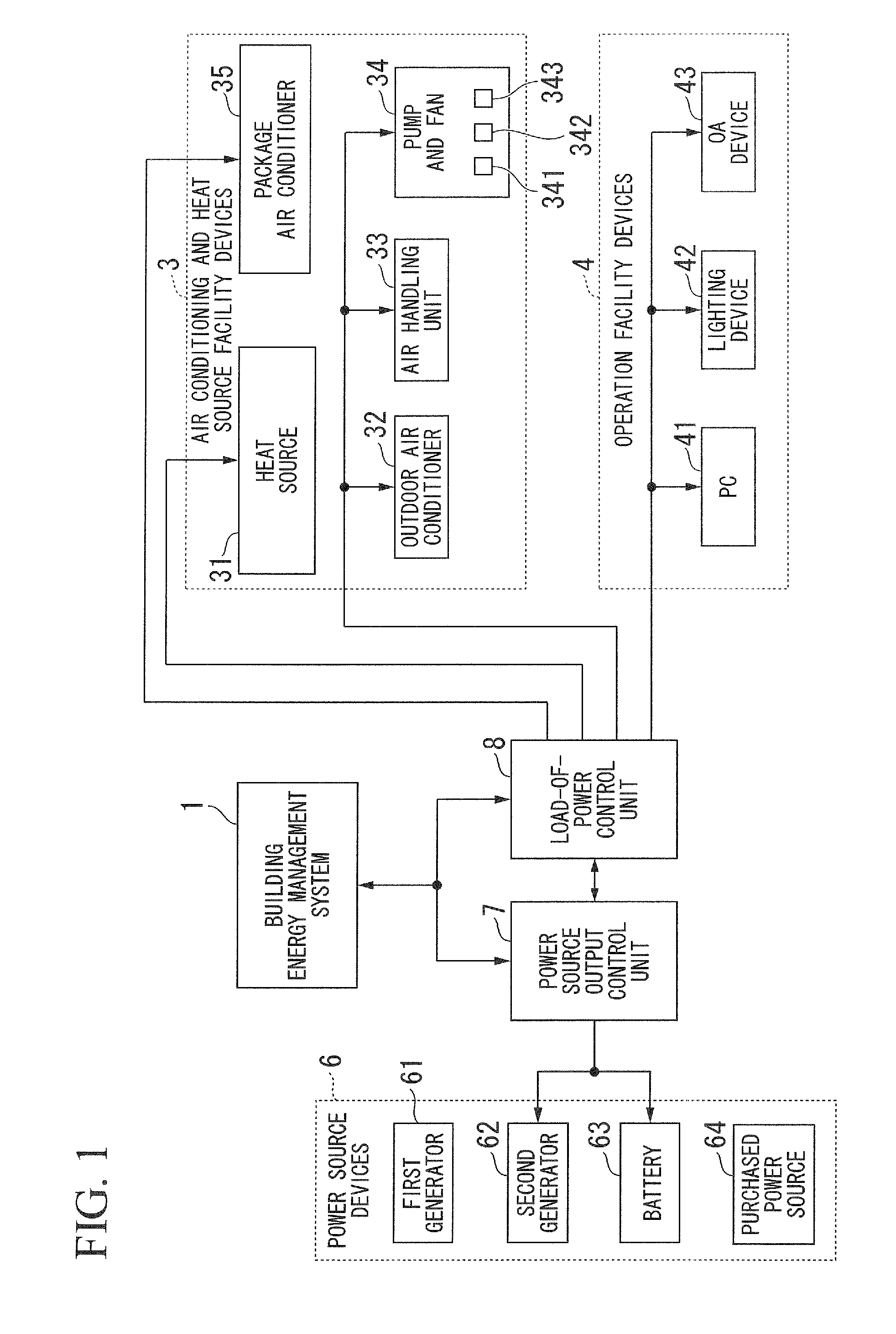
[0037]FIG. 1 is a block diagram showing an example of a configuration of a smart grid system according to a first embodiment of the present invention.

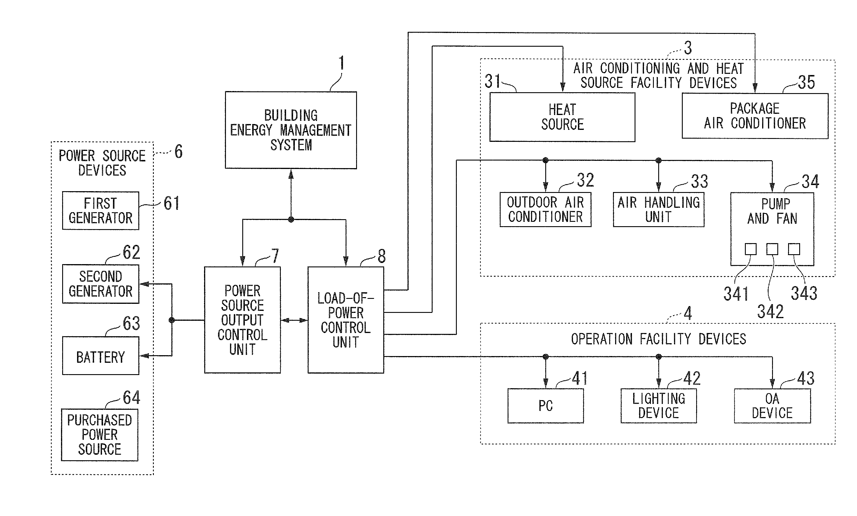
[0038]Referring to FIG. 1, the smart grid system includes the building energy management system 1, air conditioning heat source facility devices 3, operation facility devices 4, power source devices 6, a power source output control unit 7, and a load-of-power control unit 8.

[0039]The smart grid system includes the air conditioning heat source facility devices 3 and the operation facility devices 4 as a load device. Furthermore, fluctuation of a power consumption of the air conditioning heat source facility devices 3 is heavier in comparison with the operation facility devices 4 due to a heat source of the air conditioning heat source...

second embodiment

[0273]The present invention is not limited to the above-described configuration, and a configuration shown in FIG. 20 may be used. FIG. 20 is a block diagram showing an example of a smart grid system according to the second embodiment. The same reference numerals are applied to a configuration having a function similar to that of the configuration shown in FIG. 1, and thus the detailed description thereof will be omitted.

[0274]As shown in FIG. 20, the building energy management system 17 further includes a communication unit 93 in comparison with the above-described building energy management system 1. The communication unit 93 is connected to a central management apparatus 92 through a network. Power load devices 94 include the air conditioning heat source facility device 3 and the operation facility device 4.

[0275]The central management apparatus 92 includes an information acquisition unit 921, a management storage unit 922, a management control unit 923, a communication unit 924,...


PUM


Abstract

An operation management apparatus includes an air conditioning thermal load prediction unit configured to calculate an air conditioning thermal load predicted value indicating a predicted amount of heat required to adjust temperature to a pre-set temperature on a day-of-prediction, a power generation output prediction processing unit configured to calculate power generation output prediction data indicating a generated power obtained by a generator within the day-of-prediction, and an operation planning unit configured to prepare an air conditioning heat source operation plan, and determines a purchased power and the generated power using the power generation output prediction data to thereby prepare a power facility operation plan indicating a schedule of a power output from the purchased power source and the generator, so that the purchased power per predetermined time supplied from a purchased power source of a commercial power system becomes a target value.

Description

CROSS REFERENCE TO RELATED APPLICATIONS[0001]This application claims priority on Japanese Patent Application No. 2010-224127, filed Oct. 1, 2010, the contents of which are incorporated herein by reference.BACKGROUND OF THE INVENTION[0002]1. Field of the Invention[0003]The present invention relates to an operation management apparatus, an operation management method, and an operation management program, which may manages an operation plan with respect to a power supply device for supplying a power demand to a load device and the load device.[0004]2. Description of Related Art[0005]Purchased power provided by a power provider (hereinafter, referred to as power company) of a commercial power system is referred to as purchased power, and the purchased power supplied to a consumer household of the services having a load device such as a heat storage type air conditioning system, a lighting device, and the like is referred to as demand (power demand). It is necessary for the power company...

Claims


Application Information

Patent Timeline
IPC IPC(8): G06F1/32G05D23/19
CPCF24F2011/0058F24F2011/0046F24F2011/0075F24F11/0009G05B13/026H02J3/32H02J3/381Y04S20/12Y04S20/221Y04S20/242Y04S20/244F24F11/30F24F2140/50F24F2130/00F24F2130/10F24F11/46H02J2310/14H02J2300/10H02J13/00004H02J3/004Y02B70/30Y02B90/20Y04S20/222Y02B70/3225G01D2204/12G01D2204/28H02J13/00002F24F11/64F24F11/47F24F11/57F24F11/58
Inventor NAKAMURA, TAKUJIYAMANE, TOSHIHIROSHIMODA, EISUKEMORINO, KIMIO
Owner THE SHIMIZU CONSTRUCTION CO LTD
Why Eureka
Try Eureka