Methods for removing contaminants from natural gas

a technology of natural gas and contaminants, applied in the direction of gaseous fuels, lighting and heating apparatus, separation processes, etc., can solve the problems of not providing bulk removal of oxygen and nitrogen from natural gas streams, and not also removing carbon dioxide, so as to reduce the amount of oxygen removal

Inactive Publication Date: 2012-04-12
LINDE AG
View PDF9 Cites 20 Cited by
  • Summary
  • Abstract
  • Description
  • Claims
  • Application Information

AI Technical Summary

Benefits of technology

[0010]The membrane module of step b) will remove carbon dioxide in bulk. In one embodiment, a single set of membranes is employed and in a different embodiment a second set of membranes is added following the first. This second set of membranes will polish further the amount of carbon dioxide present in the natural gas stream. Certain membranes can be employed such as modified hollow fiber polyamide nitrogen membranes to remove up to half of the oxygen present in the natural gas stream as well. This will reduce the amount of oxygen removal needed in following steps.

Problems solved by technology

These processes, however, do not provide bulk removal of oxygen and nitrogen from natural gas streams, nor do they also remove carbon dioxide, all in amounts necessary to enable the natural gas to be used as a fuel source.

Method used


Image

  • Methods for removing contaminants from natural gas
  • Methods for removing contaminants from natural gas
  • Methods for removing contaminants from natural gas

Examples


Embodiment Construction

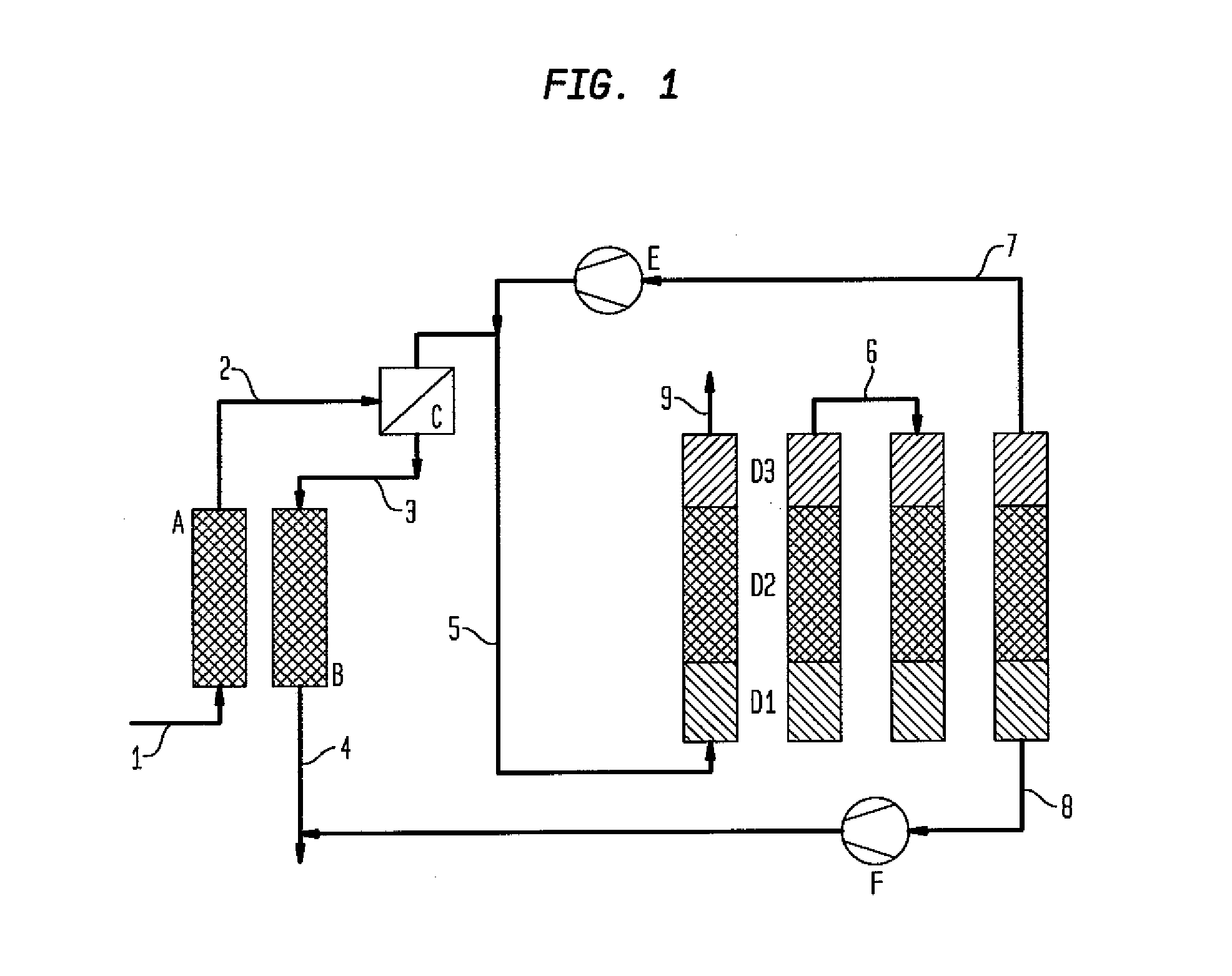
[0021]Turning to FIG. 1, natural gas is fed through line 1 to the PSA dryer bed A where water in the natural gas is removed. The dry natural gas is fed through line 2 to the membrane carbon dioxide removal unit C where much of the carbon dioxide present in the natural gas stream is removed. The permeate gas is fed through line 3 to the other PSA dryer bed B where it will regenerate bed B. The operation of beds A and B in the PSA system is such that while bed A is adsorbing water, bed B is being regenerated by the permeate gas from the membrane unit C. When their roles are reversed, bed B will adsorb water from the natural gas stream and bed A will be regenerated by the permeate gas. The regeneration gas stream will leave bed B through line 4 and can be used for power generation.

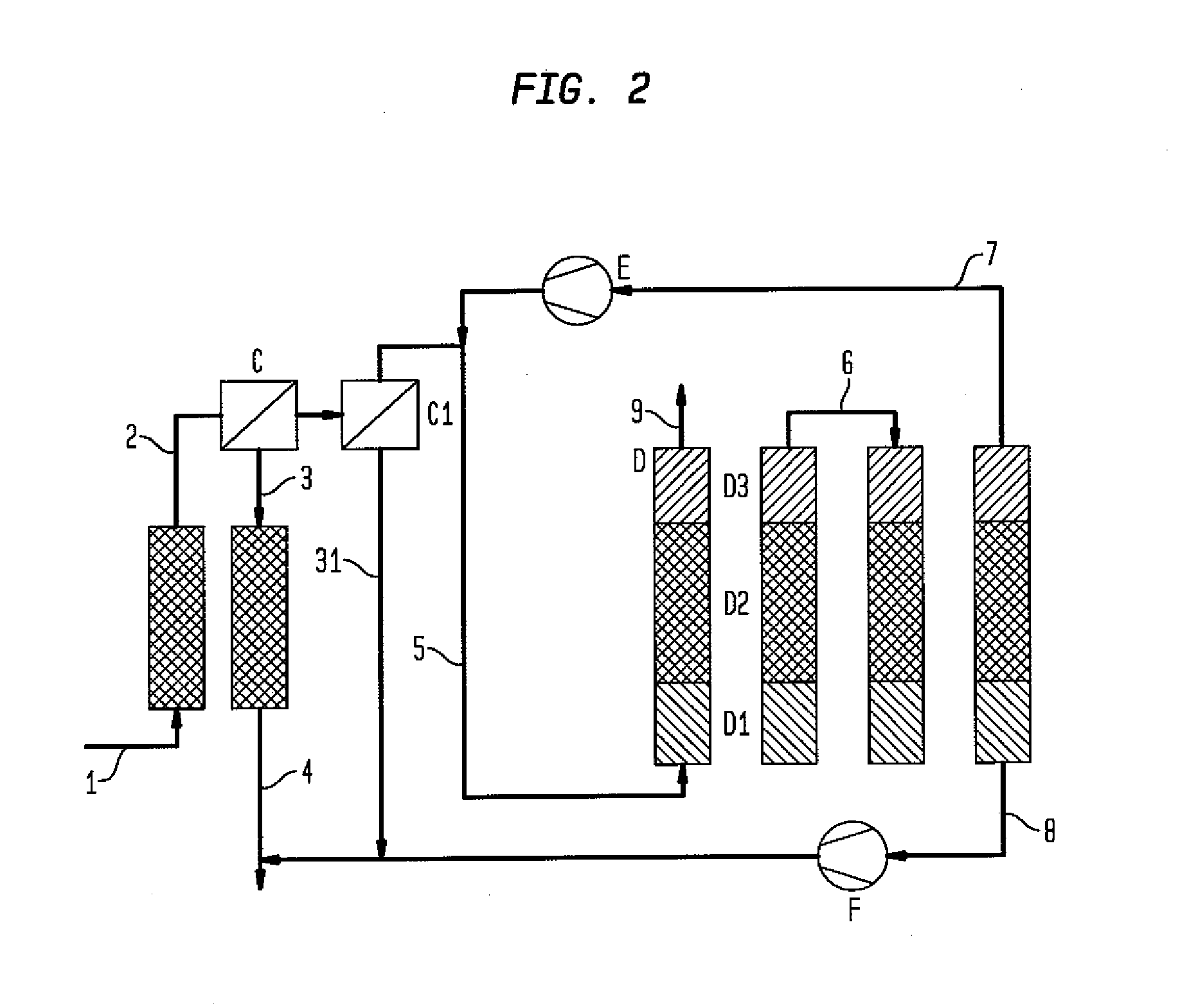
[0022]The natural gas stream will exit the membrane carbon dioxide removal unit C through line 5 and be fed to the VSA system D. Each of the four beds present in the VSA system has three layers, D1, D2 and D3...


PUM


Abstract

A method for removing contaminants from natural gas streams. The natural gas stream is fed to a dryer, then a membrane module and a multibed, multilayer vacuum swing adsorption process for removal of oxygen, nitrogen and carbon dioxide from the natural gas stream. Alternatively when carbon dioxide is in relatively low concentration in the natural gas stream, the membrane module step is not employed.

Description

CROSS REFERENCE TO RELATED APPLICATIONS[0001]This application claims priority from U.S. provisional patent application Ser. No. 61 / 331,970 filed May 6, 2010.BACKGROUND OF THE INVENTION[0002]The invention relates to a method for removing contaminant gas such as oxygen and nitrogen from natural gas. More particularly the invention provides for a method for the multi-stage removal of contaminant gases such as carbon dioxide, oxygen and nitrogen from natural gas.[0003]Natural gas is known to be extracted from underground reservoirs. The natural gas will often contain nitrogen and oxygen and other gas considered impurities. These unwanted gases could be naturally occurring or the result of a process like nitrogen injection into the reservoir as part of an enhanced oil recovery.[0004]Earlier processes have attempted the removal of these contaminant gases from natural gas. For example, a pressure swing adsorption (PSA) process separates hydrogen from natural gas by two separate PSA stages,...

Claims


Application Information

Patent Timeline
Patent Type & Authority Applications(United States)
IPC IPC(8): B01D53/047B01D53/26
CPCB01D53/0462B01D2259/40071B01D53/0476B01D53/226B01D53/229B01D2257/102B01D2257/104B01D2257/504B01D2257/80B01D2259/404B01D2259/4145C10L3/101C10L3/104C10L3/105Y02C10/08Y02C10/10B01D53/261B01D2256/245B01D2259/40062B01D53/047F25J3/0209F25J3/0233F25J3/0257F25J2200/02F25J2200/70F25J2205/60F25J2205/80F25J2210/66F25J2220/66F25J2205/40F25J2210/40F25J2215/04Y02C20/40B01D2259/402
Inventor SETHNA, RUSTAM H.KRISHNAMURTHY, RAMACHANDRAN
Owner LINDE AG
Why Eureka
Try Eureka