Method and Apparatus for Hydraulically Fracturing Wells

a technology of hydraulic fracturing and wells, which is applied in the direction of instruments, marketing, borehole/well accessories, etc., can solve the problems of too many people on site, high operating expenses of pumping service companies, and dramatic changes in the operation of pumping services

Inactive Publication Date: 2012-04-12
QIP HLDG
View PDF4 Cites 188 Cited by
  • Summary
  • Abstract
  • Description
  • Claims
  • Application Information

AI Technical Summary

Problems solved by technology

But the operations of a pumping service company change dramatically when fracturing horizontal wells.
There are too many people on location.
A well site is a dangerous place, and having 25-30 non-essential personnel on location, round the clock poses both safety issues and adds a very high operating expense to the operation.
The most dangerous activity the pumping service does today is moving such heavy equipment over the highways.
Often drivers asked to move equipment after working an “operational shift” are fatigued as they leave the well site.
This can present safety issues on the highway.
In fact, the most dangerous activity includes driving on public highways.
There are also too many trucks on location.
This requires a large footprint to accommodate so much heavy equipment and a large amount of fuel to keep the many trucks idling for weeks.
The trucks cause continuous noise pollution and diesel exhaust emissions.
Also, pumping service companies have too much capital tied up in tractors for frac spreads intended for high mobility that move only every week or two.
Because price books are not followed, there is very limited transparency to the cost of each component of the treatment, so that the operator cannot arrive at the optimum. treatment for his circumstances.
But, this decision is not possible when the cost of each component that is actually being charged an operator is not known to the operator or customer.

Method used


Image

  • Method and Apparatus for Hydraulically Fracturing Wells
  • Method and Apparatus for Hydraulically Fracturing Wells
  • Method and Apparatus for Hydraulically Fracturing Wells

Examples


Embodiment Construction

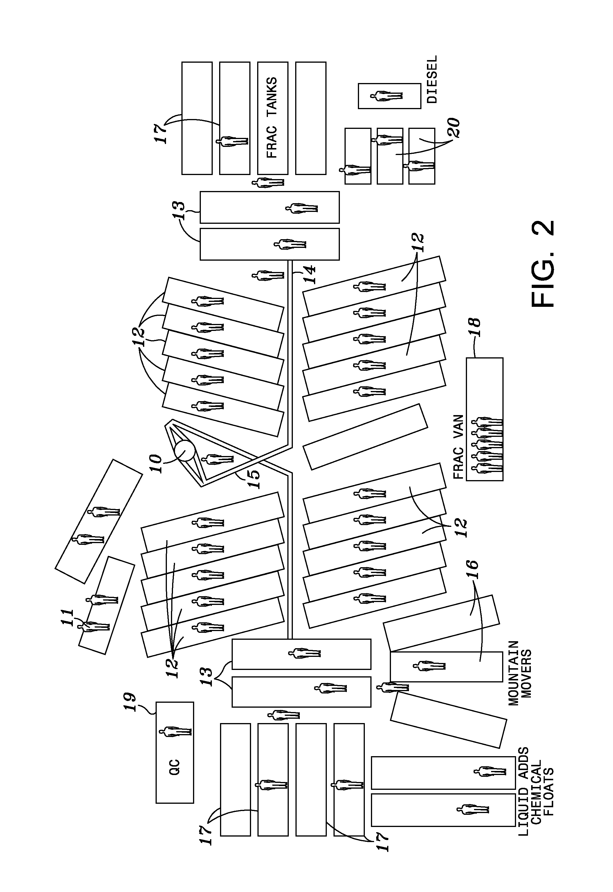
[0023]FIG. 2 is a diagram of a hydraulic fracturing spread used to hydraulically fracture well 10 using conventional methods. The formation of each fracture (each “stage”) requires injection of hundreds of thousands of gallons of fluid under high pressure supplied by pumps 12, which are normally mounted on trucks. The trucks remain at the well site throughout treatment of well 10. Manifold 14 connects pumps 12 to flow line 15, which is connected to well 10. Fluid and additives are blended in blender 13 and taken by manifold to the intake or suction of pumps 12. Proppant storage vessels 16 and liquid storage vessels 17 may be used for maintaining a supply of materials during a treatment. Wells are often fractured by 10-20 stages of fracturing treatment. The total amount of fluid pumped under high pressure is often in the range of 3-5 million gallons. Quality control tests of the fluid and additives may be performed in structure 19 before and during well treatments. Fuel for prime mov...


PUM


Abstract

A mobile plant for supplying hydraulic fracturing service to a well is provided. The plant is particularly useful for wells that require multi-stage fracturing treatments, where the surface equipment may not be moved for longer times than when supplying conventional treatments. Skid-mounted equipment is used, so that the transport vehicle for the equipment can be released after delivery of the equipment to a well site. A method for marketing and executing fracturing treatments is also provided, wherein a customer is provided price data for each item included in the total cost of a fracturing treatment, along with software for calculating the total cost of a treatment to be purchased. The customer may calculate the cost of a treatment from computer-readable storage or over the internet. The customer may also monitor the fracturing treatment remotely and obtain a post-treatment report.

Description

[0001]This application claims priority to provisional application Ser. No. 61 / 392,376 filed on Oct. 12, 2010BACKGROUND OF INVENTION[0002]1. Field of the Invention[0003]This invention relates to the hydraulic fracturing of oil and gas wells. In particular, skid-mounted equipment to form a “Mobile Frac Plant” is provided, along with an improved method for marketing and executing hydraulic fracturing operations.[0004]2. Description of Related Art[0005]Hydraulic fracturing of wells became commercial in the U.S. in 1949, using a single truck and small volumes of hydraulic fracturing fluid. The process has been continuously improved, with increasing amounts of fluid and increasing horsepower to pump the fluids into a well. A new era in hydraulic fracturing began in recent years, when it was found that wells can be drilled horizontally for large distances through shale zones and hydraulically fractured at multiple locations along the horizontal section of the well. This new capability for ...

Claims


Application Information

Patent Timeline
Patent Type & Authority Applications(United States)
IPC IPC(8): E21B43/26G06Q30/02
CPCE21B43/26G06Q30/0611G06Q30/02E21B43/2607
Inventor LOVE, DOUGLAS N.HILL, JR., THOMAS G.
Owner QIP HLDG
Why Eureka
Try Eureka