
Drill bit assembly having electrically isolated gap joint for electromagnetic telemetry

a technology of electromagnetic telemetry and assembly, which is applied in the direction of survey, manufacturing tools, borehole/well accessories, etc., can solve the problems of mechanical complexity and added cost, complex design that is necessary, and relatively expensive devices

Active Publication Date: 2012-04-12
SCHLUMBERGER TECH CORP
View PDF14 Cites 82 Cited by
  • Summary
  • Abstract
  • Description
  • Claims
  • Application Information

AI Technical Summary

Benefits of technology

The invention is a drill bit assembly that includes a bit head and a pin body connected together with an electrically insulating gap joint. The assembly also includes an electrical conductor that extends across the gap and is in contact with electronics equipment. The electrically insulating gap joint prevents electrical current from leaking between the bit head and pin body. The invention also provides a method for manufacturing the drill bit assembly. The technical effects of the invention include improved electrical insulation between the bit head and pin body, improved resistance to corrosion, and improved communication with electronics equipment.

Problems solved by technology

Nonconductive materials forming the isolation section of the gap sub typically have inherently less strength and ductility than the conductive steel materials of the drill pipe, giving rise to complex designs that are necessary to complement the structural strength of gap within the drill pipe.
Although these systems electrically isolate and seal while being subjected to drilling loads, they generally do so with a complicated multi-component design that thus becomes a relatively expensive device.
Since epoxy does not adequately seal against drilling pressures of typically 20,000 psi, additional components must be included to provide an elastomeric seal, again leading to mechanical complexity and added cost.

Method used


Image

  • Drill bit assembly having electrically isolated gap joint for electromagnetic telemetry
  • Drill bit assembly having electrically isolated gap joint for electromagnetic telemetry
  • Drill bit assembly having electrically isolated gap joint for electromagnetic telemetry

Examples


Embodiment Construction

[0049]Drill String

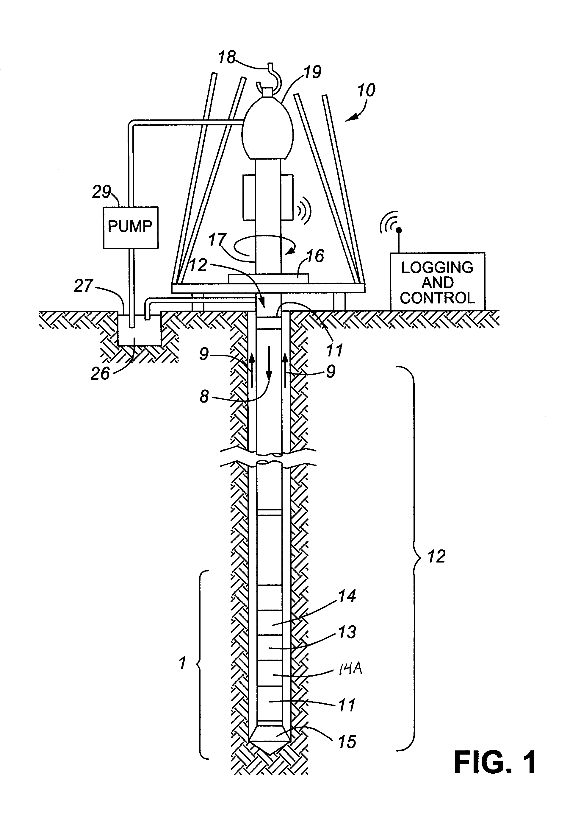
[0050]FIG. 1 illustrates a wellsite system in which a drill string 12 having a drill bit assembly 15 according to one embodiment of the invention can be employed. The wellsite can be onshore or offshore. This exemplary system depicts a vertical well but the invention is also applicable for horizontal well drilling. In FIG. 1 a borehole 11 is formed in subsurface formations by rotary drilling in a manner that is well known. Embodiments of the invention can also use directional drilling, as will be described hereinafter.

[0051]The drill string 12 is suspended within the borehole 11 and has a bottom hole assembly 1 which includes the drill bit assembly 15 at its lower end. The bottom hole assembly 1 of the illustrated embodiment comprises a measuring-while-drilling (MWD) module 13, a logging-while-drilling (LWD) module 14, a drill bit assembly 15, and a roto-steerable system and motor 17. The surface system includes platform and derrick assembly 10 positioned over the ...


PUM


Abstract

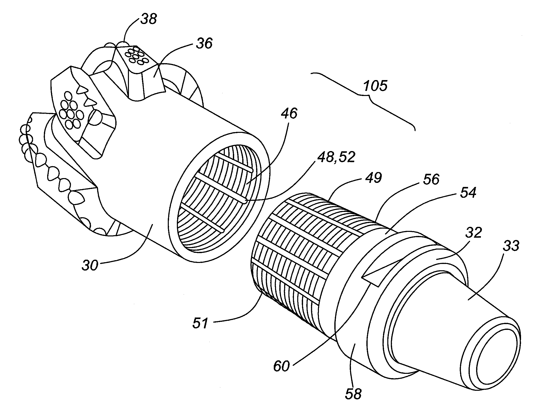
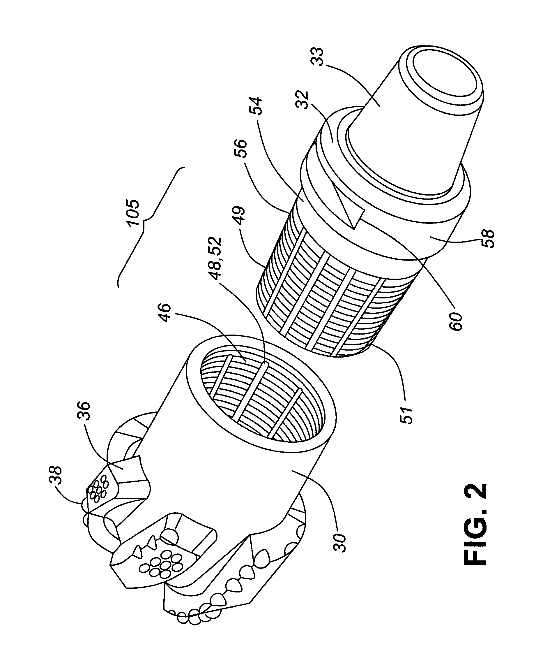
A drill bit assembly having an electrically isolated gap joint for electromagnetic telemetry comprises a drill bit, a pin body, an electrically insulating gap joint therebetween, and an electrical conductor extending across the gap joint. The bit head has a cutting end and an opposite connecting end with an engagement section. The pin body has a tubular body with an axial bore therethrough, and comprises a connecting end with an engagement section. The pin body connecting end is connected to the bit head connecting end such that the engagement sections overlap. The electrically insulating gap joint fills an annular gap between the bit head and pin body engagement sections such that the bit head and pin body are mechanically connected together at the connecting ends but are electrically separated. The electrical conductor has one end electrically contacting one of the bit head and pin body, and the other end communicable with electronics equipment.

Description

FIELD OF THE INVENTION[0001]This invention relates generally to drilling equipment used in drilling bore holes in earth formations, and in particular to a drill bit assembly having an electrically isolated gap joint used for electromagnetic telemetry and / or measuring reservoir formation properties.BACKGROUND OF THE INVENTION[0002]Modern drilling techniques employ an increasing number of sensors in downhole tools to determine downhole conditions and parameters such as pressure, spatial orientation, temperature, gamma ray count etc. that are encountered during drilling. These sensors are usually employed in logging while drilling (LWD) and ‘measurement while drilling’ (MWD). The data from such sensors are either transferred to a telemetry device, and thence up-hole to the surface, or are recorded in a memory device by logging tools to be used in a later time.[0003]One type of telemetry method is electromagnetic (EM) telemetry, which uses a downhole EM transmitter to create very low fr...

Claims


Application Information

Patent Timeline
Patent Type & Authority Applications(United States)
IPC IPC(8): E21B49/00B21K5/04E21B47/12
CPCE21B10/00E21B47/122E21B17/042E21B47/13E21B17/0285F16L25/02
Inventor LOGAN, DEREKHOLMEN, GARRYDOPF, TONYLOGAN, AARONUTTER, ROBCLARK, BRIANTAHERIAN, REZA
Owner SCHLUMBERGER TECH CORP
Learn More