Object proximity sensor recessed into imaging reader

a technology of object proximity and imaging reader, which is applied in the direction of sensing record carriers, instruments, sensing by electromagnetic radiation, etc., can solve the problems of more difficult to match the object sensing field of view with the imaging field of view, and the ambient sunlight entering the front window is susceptible to interference, so as to achieve the effect of easy matching and increased reading performan

Active Publication Date: 2012-04-12
SYMBOL TECH LLC
View PDF0 Cites 39 Cited by
  • Summary
  • Abstract
  • Description
  • Claims
  • Application Information

AI Technical Summary

Benefits of technology

[0009]In accordance with one aspect of this invention, an object sensing assembly is recessed within the reader and is supported by the rear chassis wall in spaced relation away from the window. The object sensing assembly senses the presence of an object bearing the target in front of the window by detecting return sensing light from the object through the window over a sensing field of view that at least partially overlaps the imaging field of view, and also triggers the controller to change from the standby state to the reading state upon detection of the return sensing light. The rearward, recessed mounting of the object sensing assembly makes it less susceptible to interference with ambient sunlight entering the front window. Also, the rearward, recessed mounting of the object sensing assembly makes it easier to match the object sensing field of view with the imaging field of view for increased reading performance.

Problems solved by technology

Although the known object-sensing, hands-free, imaging reader is generally satisfactory for its intended purpose, the forward mounting of the IR sensor makes it susceptible to interference with ambient sunlight entering the front window.
Also, the forward mounting of the IR sensor makes it more difficult to match the object sensing field of view with the imaging field of view for increased reading performance.

Method used


Image

  • Object proximity sensor recessed into imaging reader
  • Object proximity sensor recessed into imaging reader
  • Object proximity sensor recessed into imaging reader

Examples


Embodiment Construction

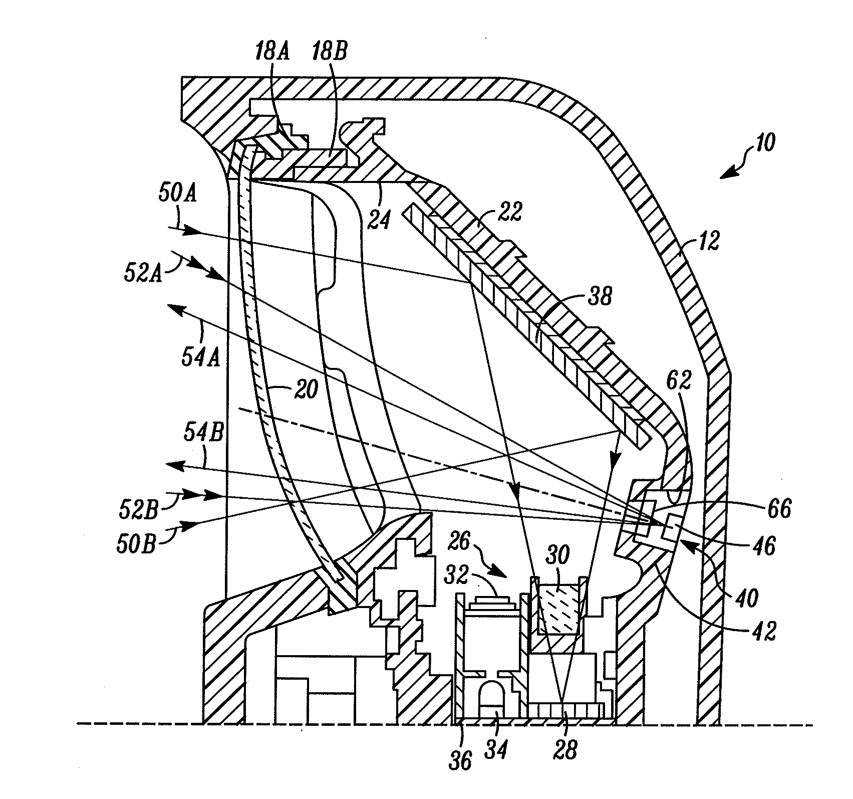
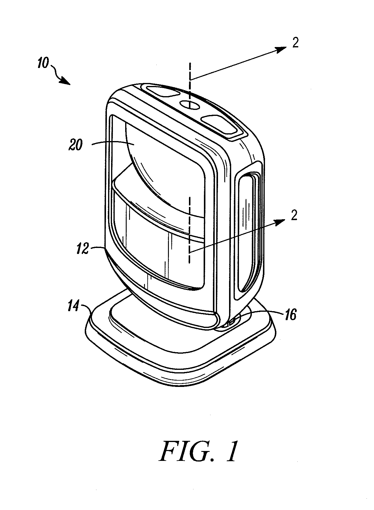
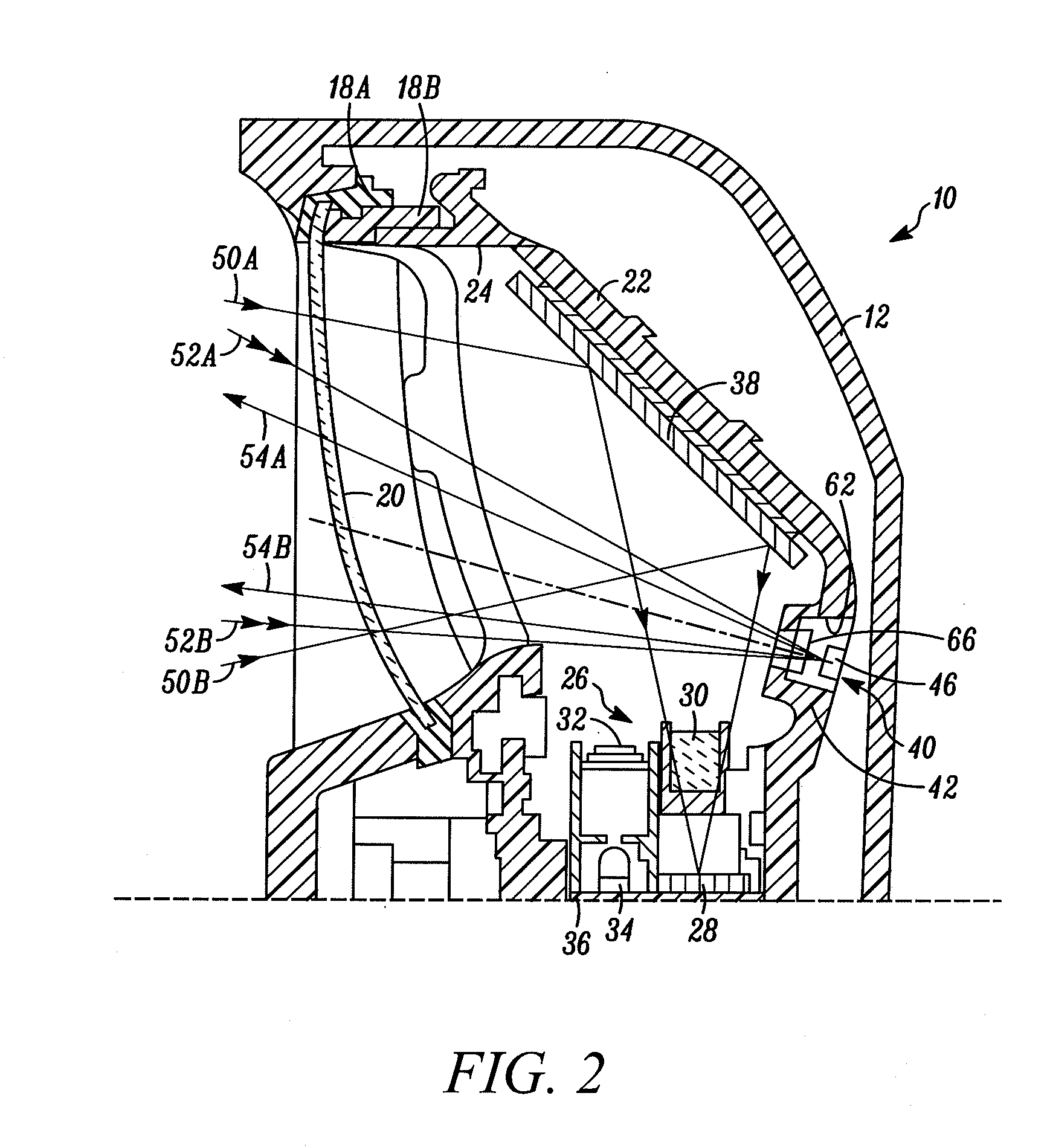
[0021]Reference numeral 10 generally identifies an imaging reader for electro-optically reading targets, such as bar code symbols, on objects, such as consumer products to be processed at a point-of-sale workstation, by image capture. The reader 10 includes a box-like housing 12 mounted on a support base 14 that rests on a countertop or like planar support surface in a hands-free mode of operation. The reader 10 can also be lifted off the support surface in a handheld mode of operation. A ratchet-type tilting mechanism 16 enables the housing 12 to be tilted to, and locked at, a desired tilt angle relative to the base 14. Other housing configurations, such as a gun-like configuration, are contemplated for use with this invention.

[0022]A light-transmissive, front window 20 is supported by the housing 12. The window 20 is a generally rectangular, injection-molded part, preferably of spherical contour, and is constituted of a non-polycarbonate, acrylic material that has good molding cha...


PUM


Abstract

An electro-optical imaging reader includes a chassis mounted in a housing, a window spaced from a rear wall of the chassis, an imaging module for capturing return light from a target through the window over an imaging field of view, a controller for operating the reader in a standby state in which no target is read, and for processing the captured return light to read the target during a reading state, and an object sensing assembly supported by the rear chassis wall and spaced from the window. The object sensing assembly senses the presence of an object bearing the target in front of the window by detecting return sensing light from the object through the window over a sensing field of view that at least partially overlaps the imaging field of view, and triggers the controller to change from the standby state to the reading state upon such detection.

Description

DESCRIPTION OF THE RELATED ART[0001]Solid-state imaging systems or imaging readers have been used, in both handheld and / or hands-free modes of operation, to electro-optically read targets to be decoded, such as one-dimensional bar code symbols, particularly of the Universal Product Code (UPC) symbology having a row of bars and spaces spaced apart along a scan direction, as well as two-dimensional symbols, such as the Code 49 symbology having a plurality of vertically stacked rows of bar and space patterns in a single symbol, and even non-symbol targets to be imaged, such as documents.[0002]The known imaging reader includes a housing either held by an operator in a handheld mode and / or supported on a support surface in a hands-free mode, a front window supported by the housing and aimed at, or facing the target, during reading, and an imaging engine or module supported by the housing and having a chassis bounding an optical compartment in which are accommodated a solid-state imager w...

Claims


Application Information

Patent Timeline
Patent Type & Authority Applications(United States)
IPC IPC(8): G06K7/14
CPCG06K7/10792
Inventor HANDSHAW, DARRANMITELMAN, YULYTRONGONE, ERICVINOGRADOV, IGORZHAO, WANCHENG
Owner SYMBOL TECH LLC
Why Eureka
Try Eureka