Arthrodesis implant apparatus and method

a technology of implanted arthroscopy and implanted bone, which is applied in the field of orthopedic surgery, can solve the problems of limited speed at which surgical procedures can proceed

Inactive Publication Date: 2012-04-12
ORTHOPRO
View PDF9 Cites 113 Cited by
  • Summary
  • Abstract
  • Description
  • Claims
  • Application Information

AI Technical Summary

Benefits of technology

[0023]In this way, the tool provides a “dogleg” effect in which the screw is axially aligned along a longitudinal axis, and the handle is collinear therewith. Meanwhile, between the handle of the tool and the threaded end of the anchor, a dogleg angles out away from the longitudinal axis, and then back in towards the longitudinal axis, aligned exactly with the longitudinal axis of the barbed portion by which the tool engages the anchor. Meanwhile, the handle end of the tool aligns at all times with the screw.

Problems solved by technology

Likewise, the speed at which surgical procedures can proceed is limited by both the physical circumstances of the injury or malady being corrected, as well as the equipment used, and any other supporting equipment or devices required by the procedure.

Method used


Image

  • Arthrodesis implant apparatus and method
  • Arthrodesis implant apparatus and method
  • Arthrodesis implant apparatus and method

Examples


Embodiment Construction

[0069]It will be readily understood that the components of the present invention, as generally described and illustrated in the drawings herein, could be arranged and designed in a wide variety of different configurations. Thus, the following more detailed description of the embodiments of the system and method of the present invention, as represented in the drawings, is not intended to limit the scope of the invention, as claimed, but is merely representative of various embodiments of the invention. The illustrated embodiments of the invention will be best understood by reference to the drawings, wherein like parts are designated by like numerals throughout.

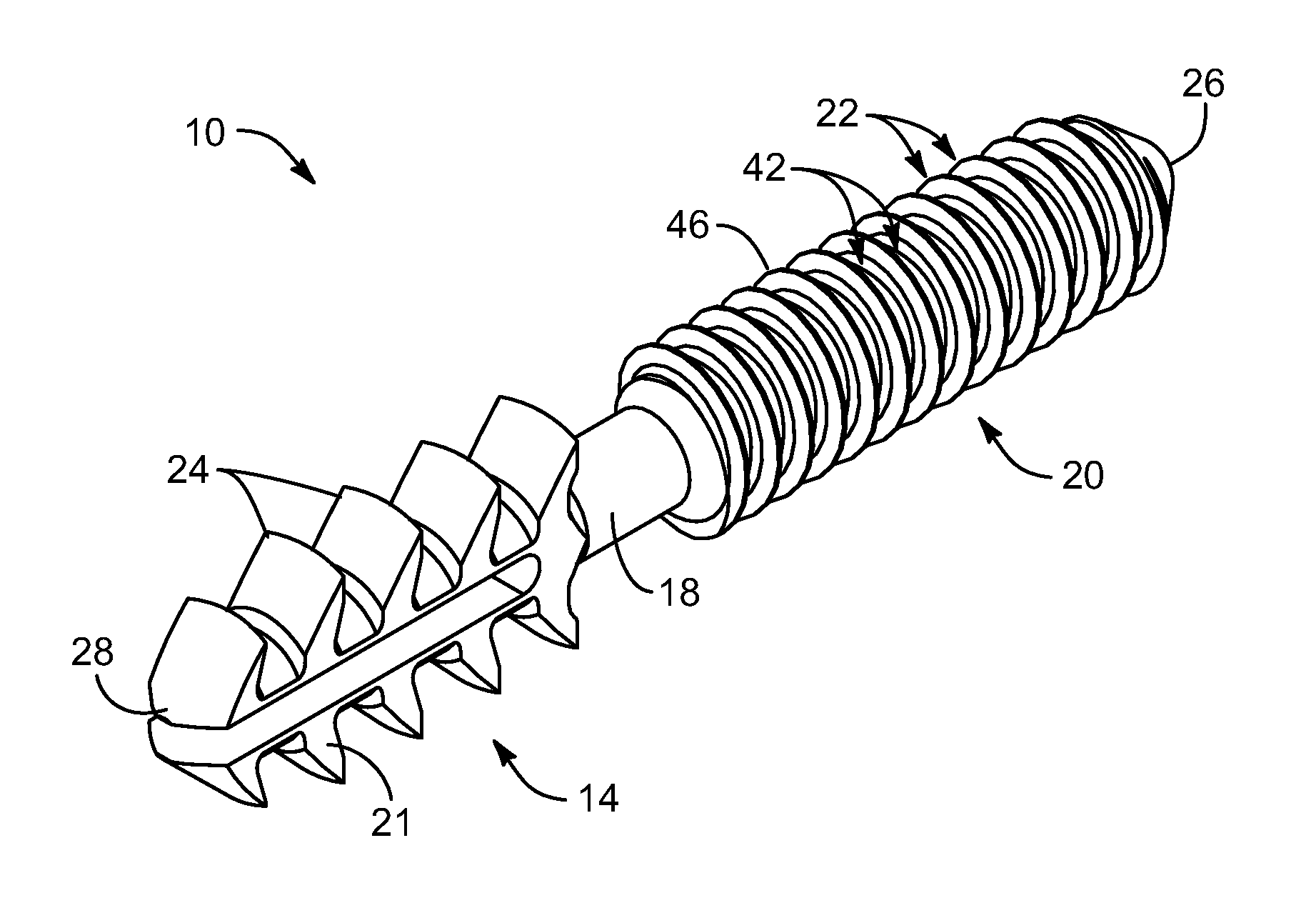
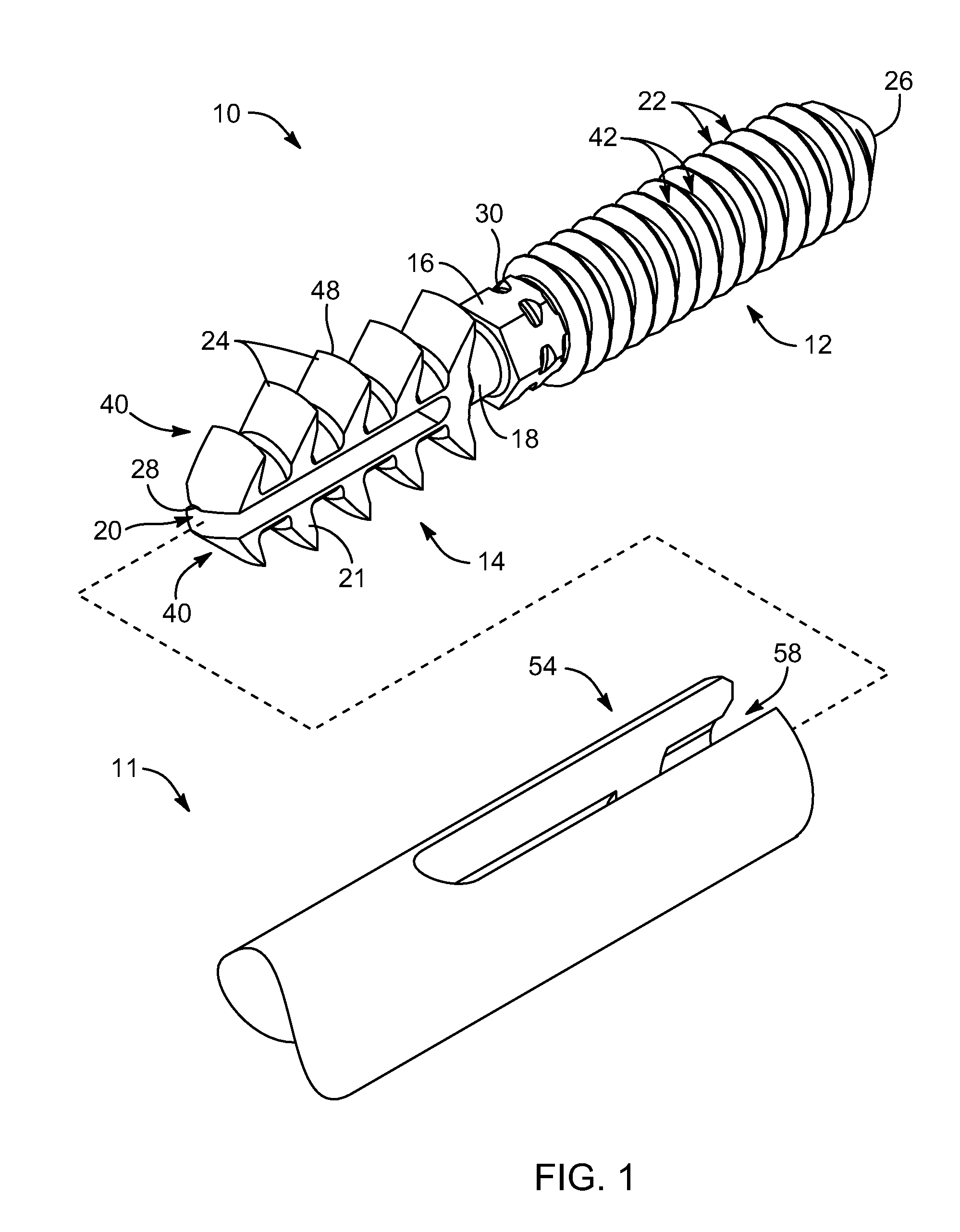
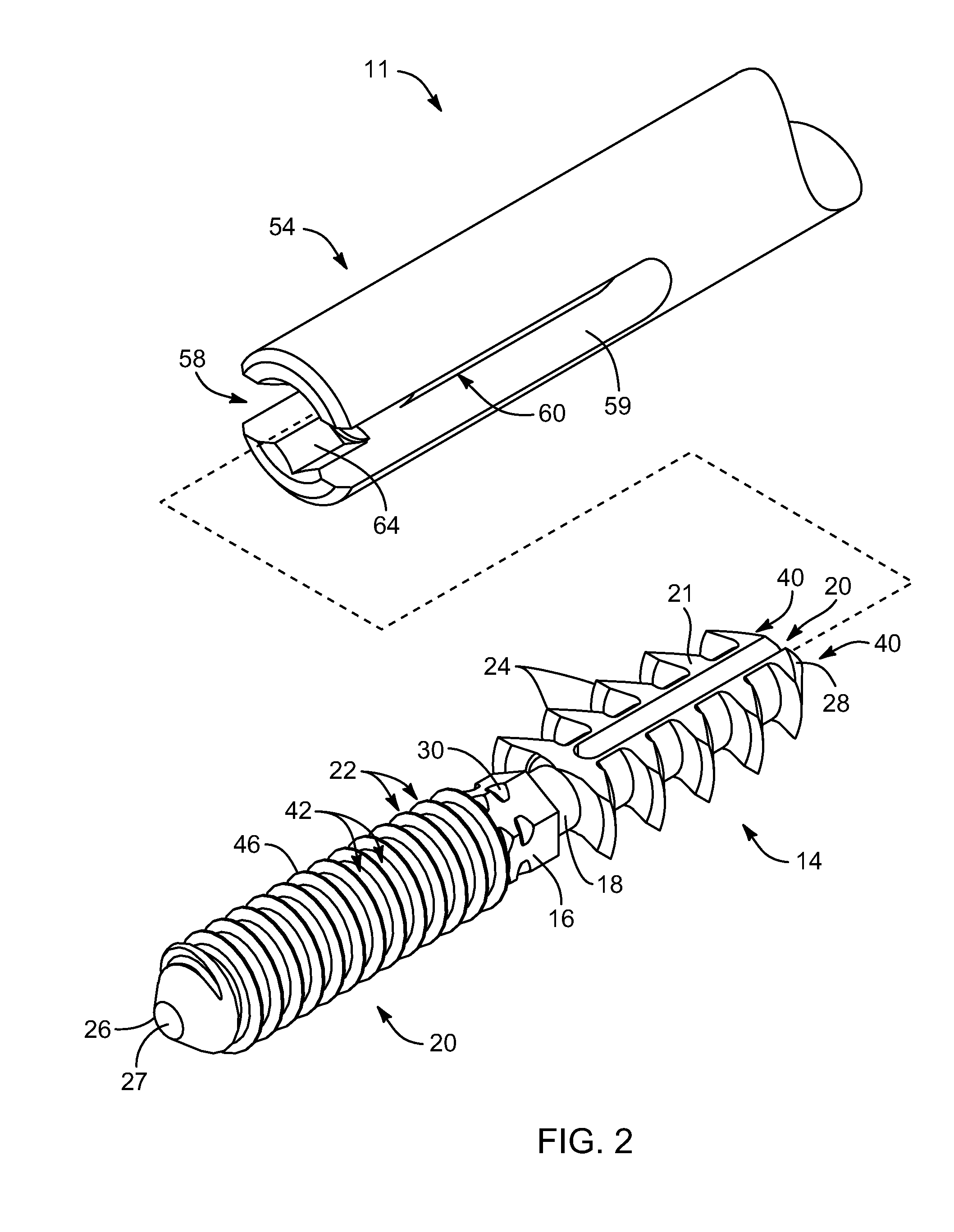
[0070]Referring to FIG. 1, while referring generally to FIGS. 1-42, a system 10 or apparatus 10 in accordance with the invention may include an anchor 10 that may be manipulated and applied using a tool 11. The anchor 10 includes a screw portion 12 or a screw 12 formed in a unit with a barb portion 14 or barb 14. In the illustra...


PUM


Abstract

An arthrodesis anchor is formed as a monolithic piece for ease of handling and use, having two ends, one of which has prongs supporting barbs extending radially therefrom. The other end may have threads or barbs. A neck between may circular in cross section and be sized from about 0.045 inches to about 0.08 inches and may be conveniently sized at 0.062 inches for bending to accommodate final alignment of joints to be bonded. Optionally, a shank next to the neck may receive a tool for threading the anchor into a joint. The proximal and intermediate phalangial joints may be trimmed and pilot drilled, after which a first end may be inserted by a tool, typically into the proximal joint by threading or linear insertion of barbed prongs. The second end having barbed prongs may then be inserted into a pilot drilled into the base of the intermediate joint.

Description

BACKGROUND[0001]1. The Field of the Invention[0002]This invention relates to orthopedic surgery and more particularly to methods and apparatus for fixing bone elements in suitable positions for permanent healing.[0003]2. The Background Art[0004]Orthopedic surgeries originated millennia ago. Anthropological excavations have demonstrated orthopedics practices evidenced in healed, sometimes structurally reinforced, bone healing. Modern orthopedic surgery has greatly advanced the art of improving deformities through surgery. Moreover, the importance of maintaining an active life has motivated demonstrably improved methods for promoting the ability to heal.[0005]For example, patients with a variety of recovery needs were customarily committed to bed rest in hospitals in decades past. Modern medicine realizes the emotional and physical toll that such inactivity takes on a patient. Modern surgical techniques acknowledge the importance of maintaining a physically active body as a mechanism ...

Claims


Application Information

Patent Timeline
Patent Type & Authority Applications(United States)
IPC IPC(8): A61B17/86
CPCA61B17/7233A61B17/8872A61B17/7291
Inventor ANDERSON, GREGORY S.
Owner ORTHOPRO
Why Eureka
Try Eureka