System for Determining the Airspeed of an Aircraft

Active Publication Date: 2012-04-12
THALES SA
View PDF0 Cites 18 Cited by
  • Summary
  • Abstract
  • Description
  • Claims
  • Application Information

AI Technical Summary

Benefits of technology

[0042]The invention notably aims to alleviate the aforementioned problems by providing a system for determining t

Problems solved by technology

These local measurements are carried out near the fuselage and are therefore subject to the disturbances generated by the latter.
These systems notably have the drawback of requiring measurement instruments, for example vanes, which are fragile, because they are light, and particularly sensitive to icing.
These systems are furthermore difficult to i

Method used


Image

  • System for Determining the Airspeed of an Aircraft
  • System for Determining the Airspeed of an Aircraft
  • System for Determining the Airspeed of an Aircraft

Examples


Embodiment Construction

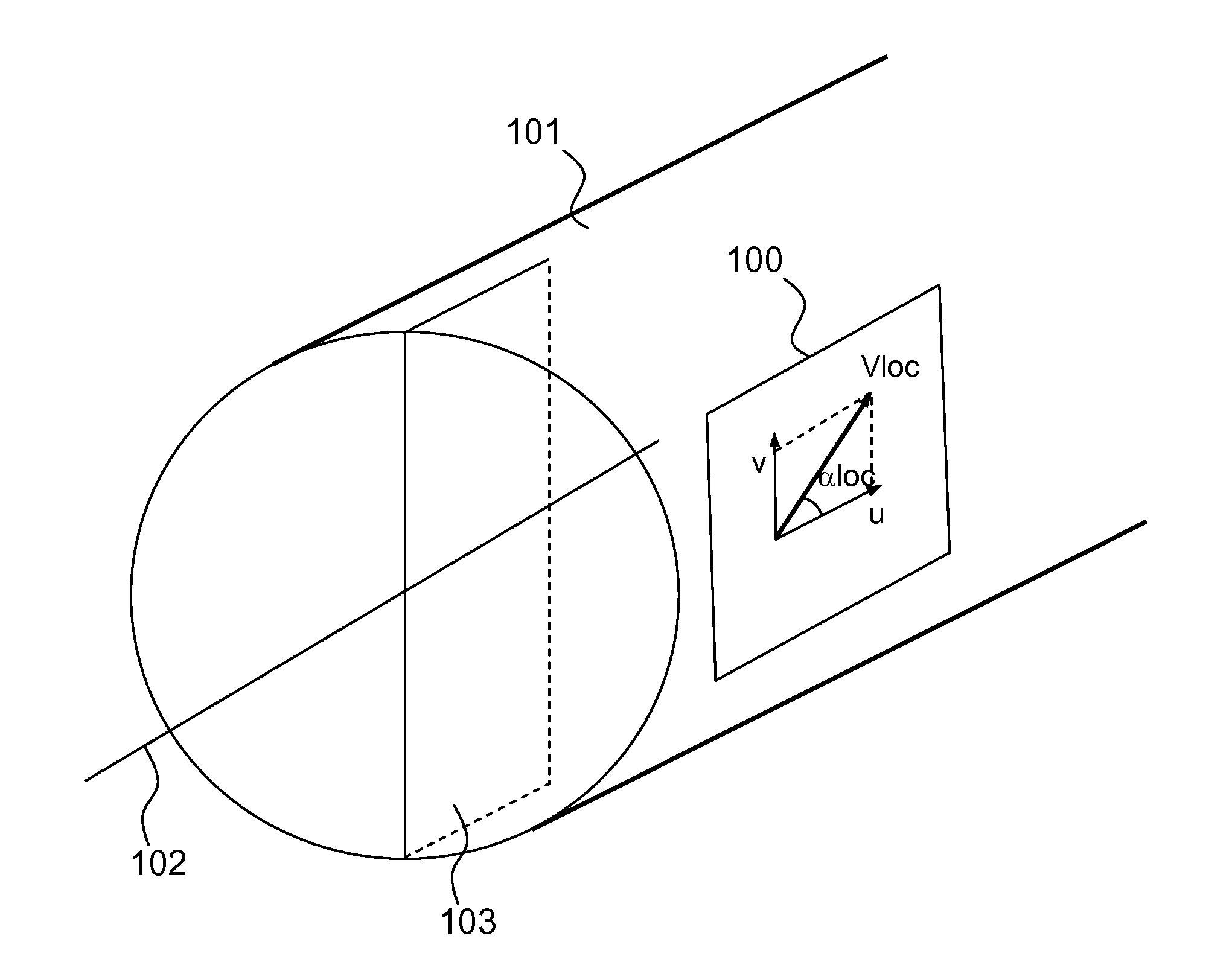
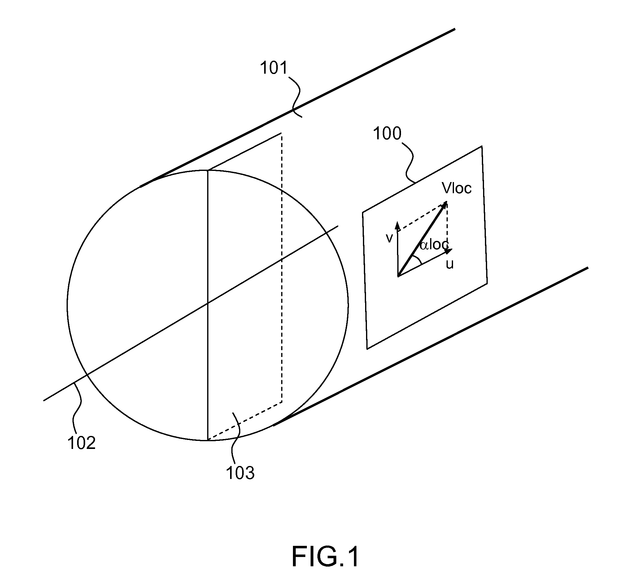
[0064]The invention makes it possible to completely characterize the velocity vector of the aircraft, i.e. its magnitude and its direction (using the angle of attack and the sideslip) on the basis of at least four measurements of local speed components.

[0065]FIG. 4 shows an exemplary embodiment of the measurement system according to the invention.

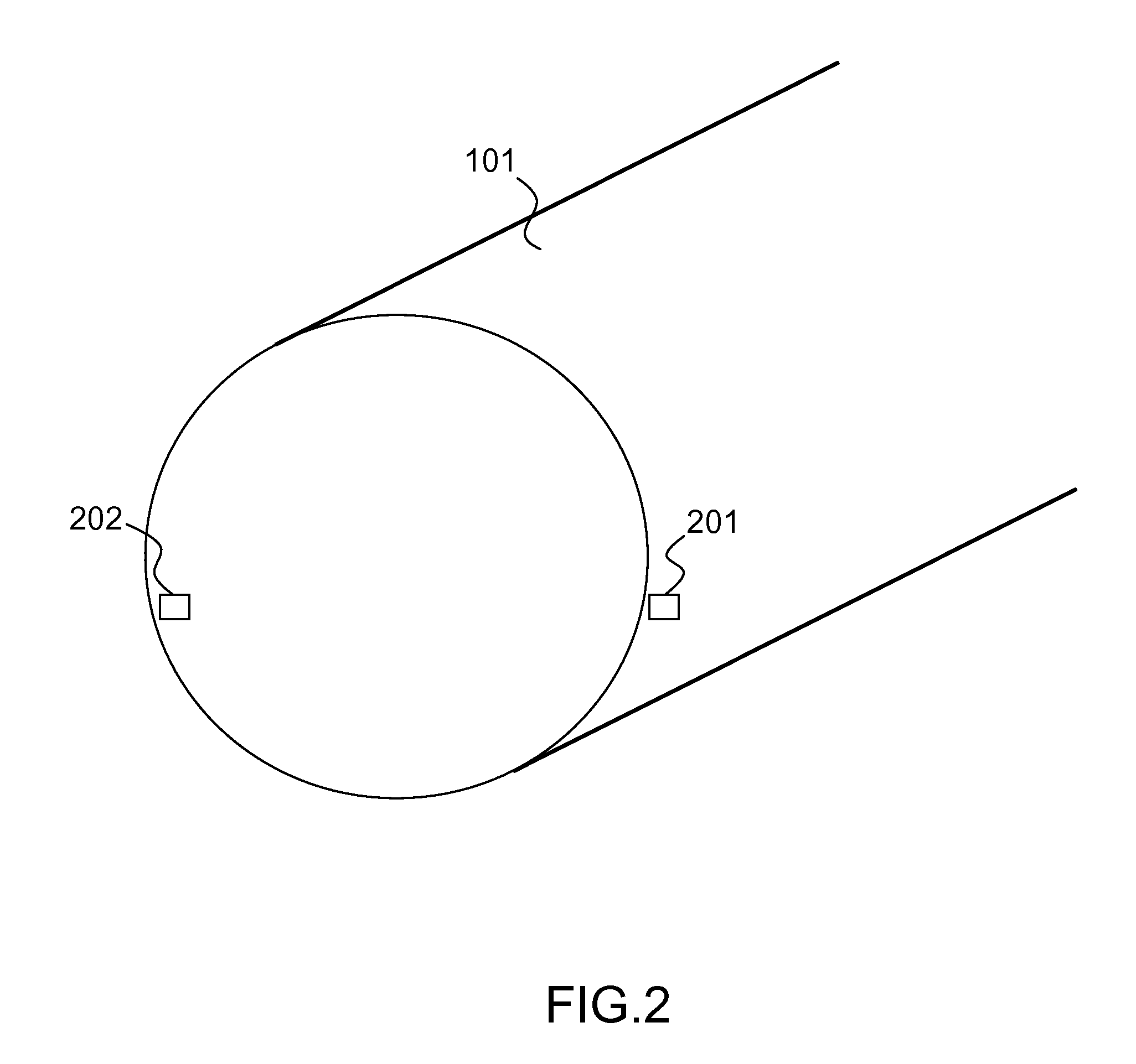
[0066]The system comprises four laser anemometers 401, 402, 403, 404 distributed around the fuselage 101 of the aircraft, measuring a component of the true airspeed and being positioned in various locations around the fuselage 101 of the aircraft.

[0067]The system also comprises means for calculating the true airspeed of the aircraft using the four measurements of local components of the true airspeed.

[0068]The anemometers may be placed in separate locations anywhere on the fuselage. There are however advantageous positions that make the calculations performed by these measurements easier.

[0069]Advantageously, the first 401 and the second 40...


PUM


Abstract

A system for determining the true airspeed vector, defined by a magnitude and by a direction, of an aircraft comprising a fuselage, comprises four laser anemometers each having a single measurement path so as to measure a local component of the true airspeed and being distributed in different locations around the fuselage of the aircraft; and means for calculating the magnitude and direction of the true airspeed vector of the aircraft using the four measurements of components of the true airspeed.

Description

CROSS-REFERENCE TO RELATED APPLICATION[0001]This application claims priority to foreign French patent application No. FR 1003994, filed on Oct. 8, 2010, the disclosure of which is incorporated by reference in its entirety.FIELD OF THE INVENTION[0002]The invention relates to the field of anemometer measurements onboard fixed-wing aircraft.BACKGROUND[0003]Onboard anemometer measurements notably aim to determine the following values located at infinity upstream: the true airspeed (or TAS), the angle of attack, the sideslip, the calibrated airspeed and the static pressure of the aircraft or the pressure altitude.[0004]It will be recalled that:[0005]the true airspeed V is the speed of an aircraft relative to undisturbed air;[0006]the angle of attack is the angle α formed between the velocity vector V of the aircraft and the longitudinal axis;[0007]the sideslip is the angle between the velocity vector V and the (vertical) plane of symmetry of the aircraft;[0008]the static pressure (Ps) is...

Claims


Application Information

Patent Timeline
IPC IPC(8): G06F15/00G01S17/87
CPCG01P5/26G01P13/025G01S17/95G01S17/87G01S17/58Y02A90/10
Inventor MANDLE, JACQUES
Owner THALES SA
Why Eureka
Try Eureka