Error correction encoding apparatus, decoding apparatus, encoding method, decoding method, and programs thereof

a technology of error correction and encoding apparatus, applied in the direction of redundant data error correction, coding, code conversion, etc., can solve the problems of large increase in encoding gain in accordance with the increase in frame length, complicated decoding processing and the device for achieving the processing, etc., to achieve suppressed power consumption, greatly improved encoding gain, and increased decoding processing speed

Active Publication Date: 2012-04-12
NEC CORP
View PDF6 Cites 17 Cited by
  • Summary
  • Abstract
  • Description
  • Claims
  • Application Information

AI Technical Summary

Benefits of technology

[0026]As described above, the present invention is basically structured to execute the encoding by a plurality of combinations such as executing encoding by one of the encoding modules by using the m-stage quasi-cyclic low density parity check encoding method and further encoding the replaced output of the redundant sequence via the data replacing module by using the other encoding module. This makes it possible to provide such an excellent effect that the encoding gain is greatly improved by the increase in the frame length.
[0027]Further, when decoding the encoded data sequence, the same decoding processing corresponding to the m-stage quasi-cyclic low density parity check codes as in the case of the transmission data sequence encoding described above is executed on the receiver side even when data sequence of the increased frame length is transmitted. Thus, it is possible to perform the decoding processing without increasing the circuit scale and the number of memories to be used. This provides excellent effects of increasing the speed of the decoding processing and suppressing the power consumption at the time of the decoding processing operations.

Problems solved by technology

Regarding the sum-product and min-sum algorithm as the decoding methods of the low density parity check codes, decoding processing and the device for achieving the processing tend to become complicated as the stage number m becomes smaller with respect to the natural number n.
However, with the low density parity check codes of such structure in general, a large increase in the encoding gain in accordance with the increase in the frame length cannot be expected.

Method used


Image

  • Error correction encoding apparatus, decoding apparatus, encoding method, decoding method, and programs thereof
  • Error correction encoding apparatus, decoding apparatus, encoding method, decoding method, and programs thereof
  • Error correction encoding apparatus, decoding apparatus, encoding method, decoding method, and programs thereof

Examples


first exemplary embodiment

[0040]Next, a first exemplary embodiment of an error correction encoding apparatus and a decoding apparatus corresponding to the encoding apparatus according to the present invention will be described by referring to FIG. 1 to FIG. 9.

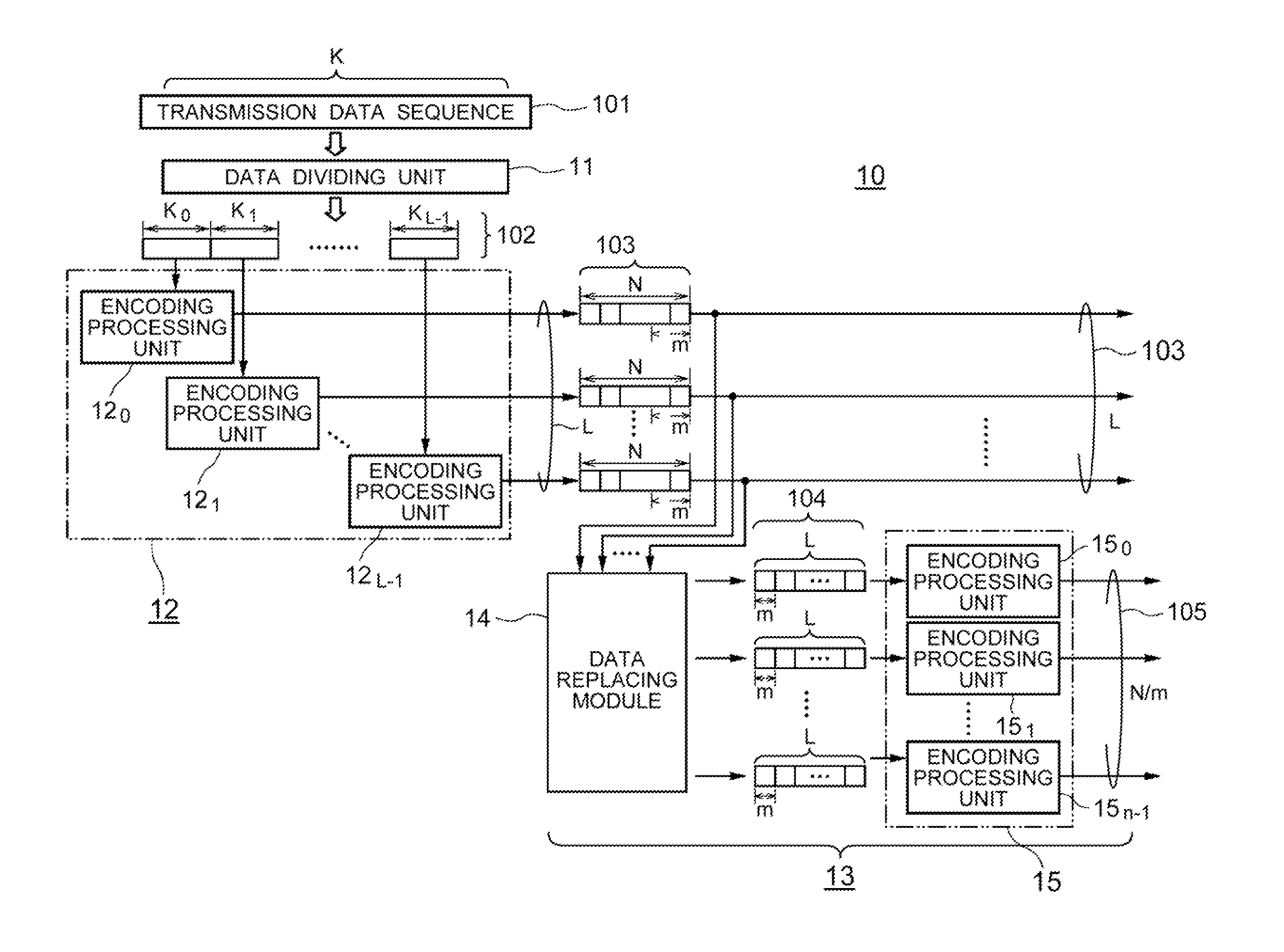
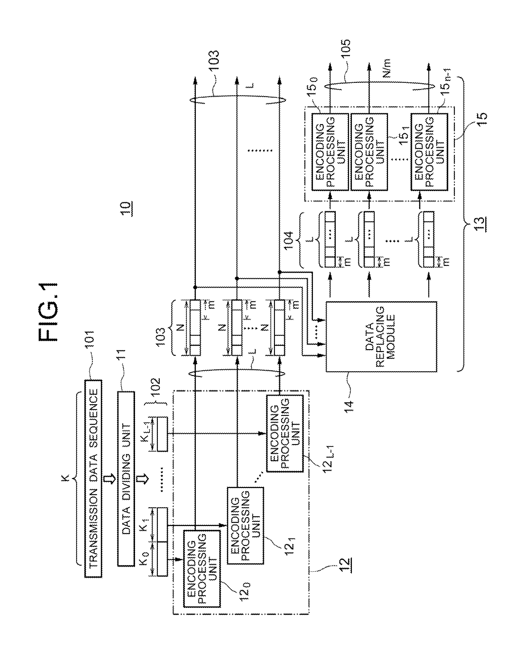
[0041]The encoding apparatus according to the first exemplary embodiment includes a transmission data sequence input module which inputs transmission data sequence of a length K and a redundant sequence calculating module which calculates a redundant sequence from the inputted transmission data sequence, and the encoding apparatus is structured to output the redundant sequence and the transmission data sequence towards the corresponding decoding apparatus to perform decoding.

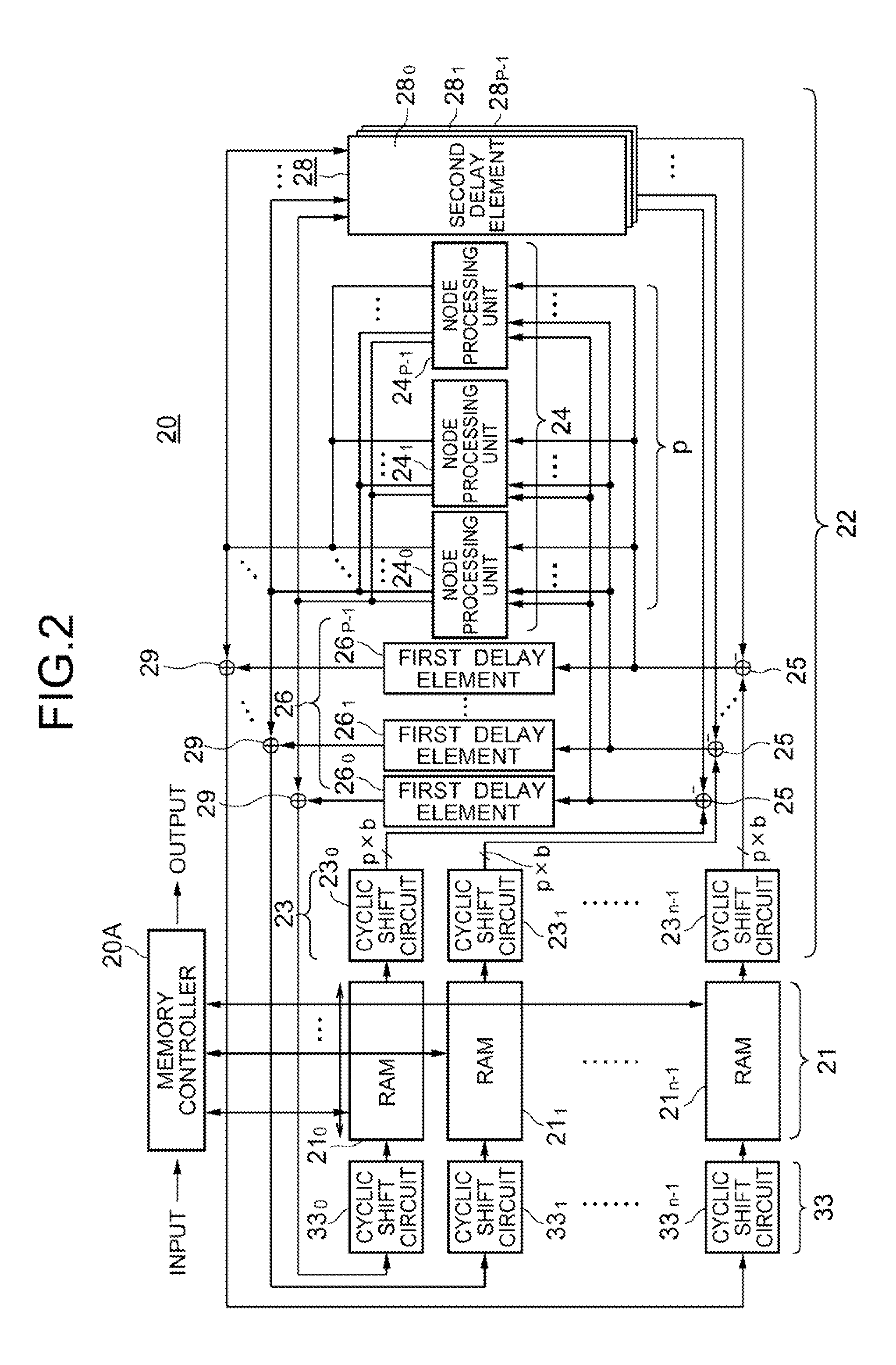
[0042]The error correction encoding apparatus 10 according to the first exemplary embodiment is shown in FIG. 1, and the decoding apparatus 20 which decodes and outputs the encoded data outputted from the encoding apparatus 10 is shown in FIG. 2.

(Structure of Error Correction Encodi...

second exemplary embodiment

[0151]Next, a second exemplary embodiment of the present invention will be described by referring to FIG. 10.

[0152]Note here that the same reference numerals are applied to the same structural members as those of the first exemplary embodiment.

[0153]The second exemplary embodiment is so characterized that a decoding apparatus 20 includes an integration circuit (an integration device) 34 shown in FIG. 10 instead of the minimum-value calculating module provided as each of the node processing units 240, 241, 242, - - - , 24p 1 which constitute the node processing module 24. Other structures are the same as the contents disclosed in FIG. 2 described above. Further, the encoding apparatus 10 disclosed in FIG. 1 is also employed to the second exemplary embodiment without any changes.

[0154]The integration circuit 34 shown in FIG. 10 includes a plurality of adders 34A, first and second conversion tables 34B, 34F, exclusive OR circuits 34C, and subtractors 34E by corresponding to each of a p...

third exemplary embodiment

[0164]Next, a third exemplary embodiment of the present invention will be described by referring to FIG. 11.

[0165]The third exemplary embodiment is characterized to use a first replacing module 14 as the data replacing module in the error correction encoding apparatus 10 disclosed in FIG. 1 and to additionally provide a second replacing module 44 which inputs each parity part of length s×m of N / m-pieces of encoded sequences encoded by the second encoding module 15, changes the order thereof, and outputs S-pieces of sequences of length N.

[0166]Further, there is also provided a third encoding module 45 which includes a plurality of encoding processing units for encoding a part of the S-pieces of sequences of length N as the outputs of the second replacing module 44 with the quasi-cyclic low density parity check codes of m-stages and length N.

[0167]Furthermore, each of the parity parts encoded by the third encoding module 45 is outputted as the encoded transmission data like the L-piec...


PUM


Abstract

Provided is an encoding apparatus wherein a transmission data sequence is divided into L short sequences, each of which is then encoded by use of an m-stage pseudo-cyclic low-density parity check encoding system. Each of the L encoded sequences is further divided into shorter sequences, the number of which is identical to the number m of the stages of the pseudo-cyclic codes and each of which has a length m. The shorter sequences are rearranged in order by a replacing module, thereafter encoded, by use of the m-stage pseudo-cyclic low-density parity check encoding system, and outputted. Accordingly, a decoding apparatus with a simple structure where node processing circuits (e.g., minimum-value calculating circuits), the number of which is p that is a submultiple of the number m of the foregoing stages, are provided, can be employed to efficiently decode the codes having a large frame length and a large encoding gain.

Description

TECHNICAL FIELD[0001]The present invention relates to an error correction encoding apparatus, a decoding apparatus, and the like. More specifically, the present invention is based on quasi-cyclic low density party check (LDPC), which relates to a an error correction encoding apparatus for correcting block errors which divides an information sequence into blocks of a specific length and adds a redundant sequence individually to each block, and to a decoding apparatus, an encoding method, a decoding method, as well as programs thereof.BACKGROUND ART[0002]In satellite communications, mobile telecommunication systems, or the like, an error correction encoding technique exhibiting a large encoding gain is employed in order to satisfy requirements in terms of the system structures such as reduction of required power, reduction in the size of antennas, and the like. In such case, low density parity check (LDPC) codes are known as an error correction codes exhibiting a large encoding gain, ...

Claims


Application Information

Patent Timeline
Patent Type & Authority Applications(United States)
IPC IPC(8): H03M13/05G06F11/10
CPCH03M13/116H03M13/1111
Inventor KAMIYA, NORIFUMI
Owner NEC CORP
Why Eureka
Try Eureka