Auger for digging holes

Active Publication Date: 2012-04-19
DANUSER
View PDF5 Cites 6 Cited by
  • Summary
  • Abstract
  • Description
  • Claims
  • Application Information

AI Technical Summary

Benefits of technology

[0006]It is an object of the present invention to provide an auger that effectively digs a post hole while limiting the amount of loose soil generated from the digging of the post hole. An embodiment of the auger of the present invention comprises an elongated shaft body having a tapered end. The lateral surface of the shaft body is without helical flighting elements such that the ground in which the auger is inserted is effectively pushed outwardly to form the post hole, rather than excavated. The inventive auger limits the generation of loose soil which would otherwise remain in the post hole or be conveyed out of the post hole.
[0009]It is another embodiment of the present invention to provide a method by which to dig a post hole that minimizes the amount of loose dirt generated by the creation of the post hole.

Problems solved by technology

Ensuring the soil is properly compacted and removing the excavated overburden soil can be very time consuming and labor intensive.
Although the auger's helical flighting effectively scrapes away earth to form the excavated post hole, the cutting action disturbs the stability of the hole wall and leaves the remaining wall subject to crumbling and degradation.

Method used


Image

  • Auger for digging holes
  • Auger for digging holes
  • Auger for digging holes

Examples


Embodiment Construction

, below.

DESCRIPTION OF THE DRAWINGS

[0012]Further features of the present invention will become apparent to those skilled in the art to which the present invention relates from reading the following description with reference to the accompanying drawings, in which:

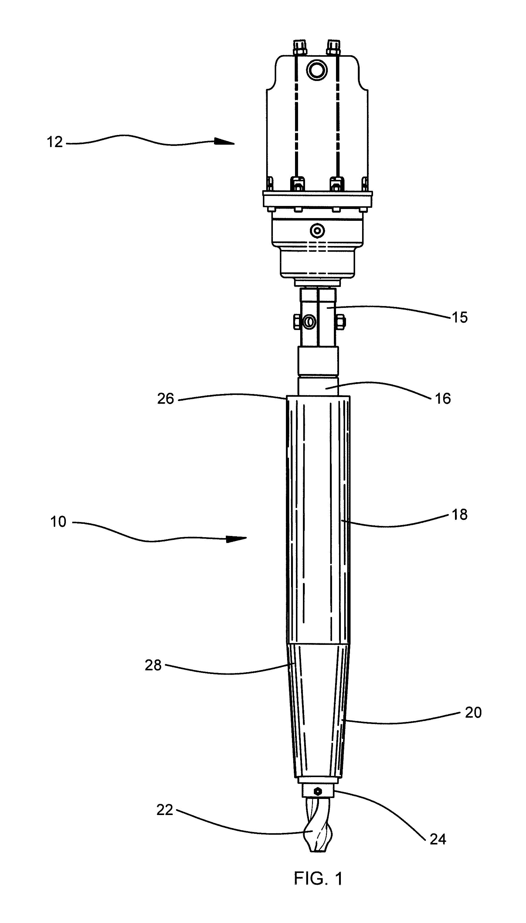
[0013]FIG. 1 is view in side elevation of an embodiment of the auger of the present invention.

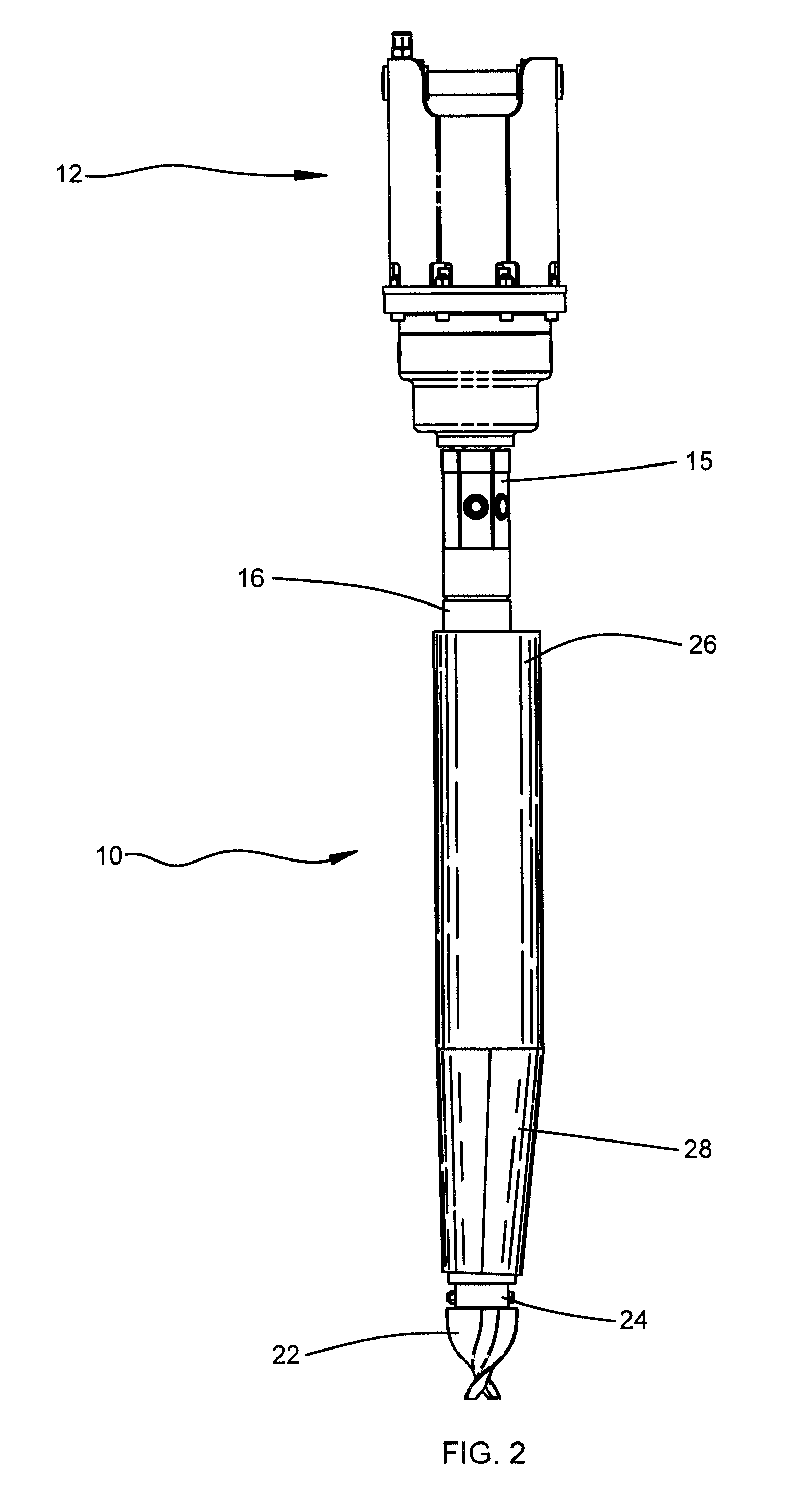
[0014]FIG. 2 is a view similar to FIG. 1 but rotated 90° to the left about the vertical axis.

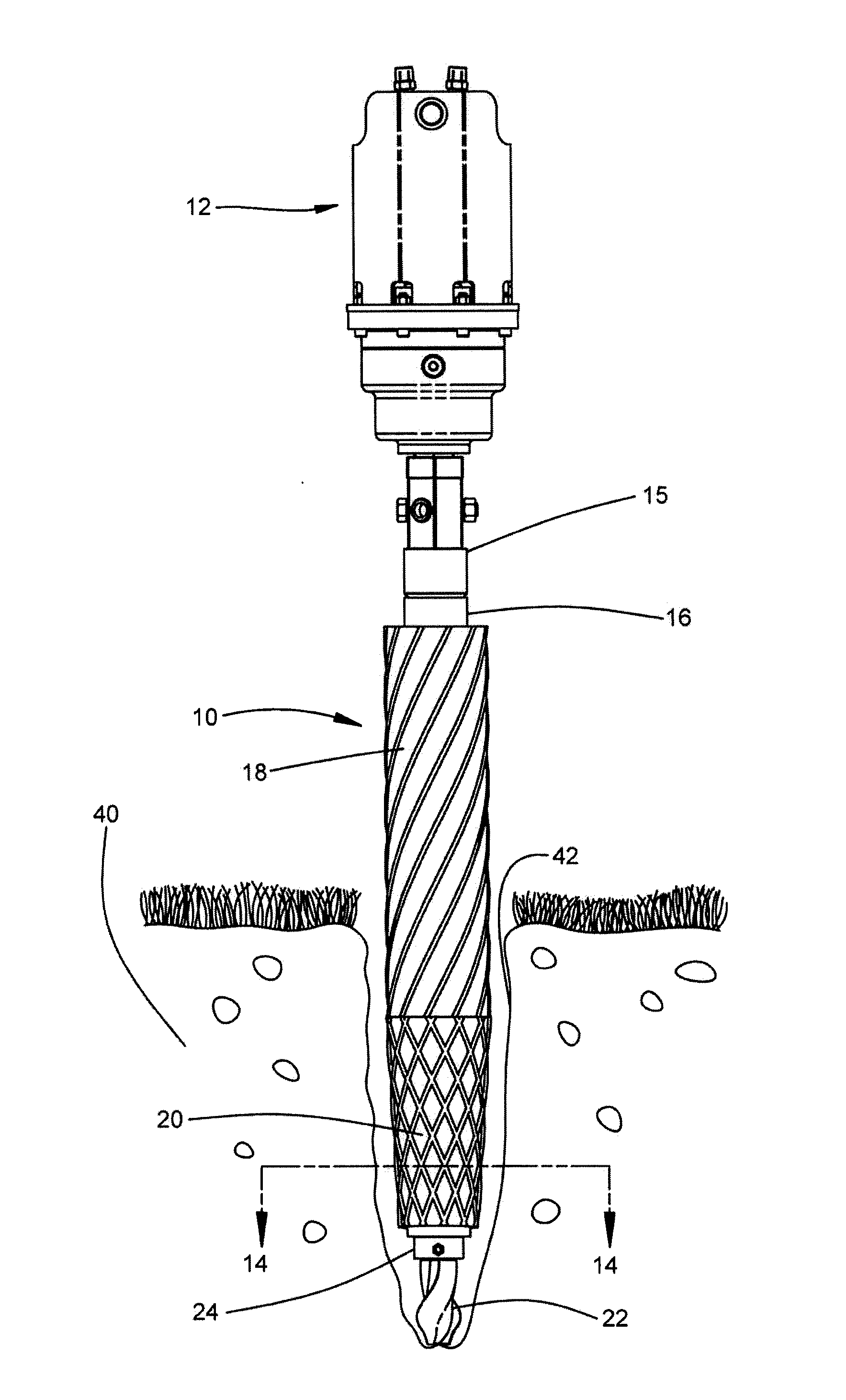
[0015]FIG. 3 is a view in side elevation of another embodiment of the auger.

[0016]FIG. 4 is a cross-sectional view of an embodiment of the auger in side elevation taken along lines 4-4 in FIG. 3.

[0017]FIG. 5 is a cross-sectional view taken along lines 5-5 in FIG. 3.

[0018]FIG. 6 is a view similar to FIG. 5 but rotated 90° clockwise.

[0019]FIG. 7 is a view similar to FIG. 6 but rotated 90° clockwise.

[0020]FIG. 8 is a view similar to FIG. 7 but rotated 90° clockwise.

[0021]FIG. 9 is a cross-sectional view taken along lines 9-9 in FIG. 3.

[0022]FI...


PUM


Abstract

An auger for digging holes that minimizes the amount of loose dirt excavated in and around the dug hole. The auger comprises an elongated shaft body whose axial longitudinal center is disposed in a parallel offset position from the axial engagement line of orientation with the driving source for rotationally driving the auger. The shaft body of the auger revolves in an eccentric lateral orbit as the auger rotates which digs the hole by pushing and widening the dirt in the hole rather than cutting and scraping. The distal end of the auger has a tapered configuration for initial penetration into the ground. The eccentric movement of the shaft body of the auger helps to compact the walls of the hole being dug.

Description

RELATED APPLICATIONS[0001]The present non-provisional patent application claims priority benefit of an earlier-filed provisional patent application of the same title, Ser. No. 61 / 392,616, filed Oct. 13, 2010. The identified earlier-filed application is hereby incorporated by reference into the present application.FIELD OF THE INVENTION[0002]The present invention relates to digging equipment, and in particular, augers for digging holes in the ground. More particularly, the present invention relates to drilling post holes for fence posts or utility poles.BACKGROUND OF THE INVENTION[0003]A variety of methods are utilized to produce a post hole, involving both mechanized and non-mechanized means. Mechanized post hole diggers generally comprise a rotating auger having helical flighting and a cutting head to aid in loosening the soil to be excavated. As the auger rotates, the loosened soil is conveyed out of the hole by the screw-like movement action of the helical flighting formed into t...

Claims


Application Information

Patent Timeline
IPC IPC(8): E21B7/00E21B10/44
CPCE21B10/26E21B10/265
Inventor NIEKAMP, GARY J.
Owner DANUSER
Why Eureka
Try Eureka