Flexible middle layer for RFID patch on tires

a technology of flexible middle layer and tire, which is applied in the direction of instruments, other domestic objects, transportation and packaging, etc., can solve the problem that no design generally encompasses all of the desired characteristics

Inactive Publication Date: 2012-04-19
MICHELIN & CO CIE GEN DES ESTAB MICHELIN +1
View PDF8 Cites 22 Cited by
  • Summary
  • Abstract
  • Description
  • Claims
  • Application Information

AI Technical Summary

Benefits of technology

[0010]According to another exemplary embodiment of the present invention, a method of fabricating a tire mountable apparatus is disclosed. The method includes mixing a potting compound and placing the potting compound on a first layer of uncured material to form a middle layer. The method further includes coating an electrical device in the potting compound and placing the electrical device in the middle layer. The method further includes placing a second layer of uncured material on top of the middle layer and curing the middle layer between the first layer and the second layer to form the tire mountable apparatus. The potting compound does not require exposure to heat, air, moisture or light and does not require solvent evaporation or outgassing of reaction products to cure.

Problems solved by technology

Stresses over time caused by the RFID tag or other electrical device during, for example, tire rotation may create openings and tears in the rubber or polymeric patch layers Such openings are undesirable because they may, for instance, admit water or other substances into the patch which could cause damage to the RFID tag or other electrical device.
While various implementations of RFID tags and other electrical devices in tires have been developed, and while various methods of mounting the RFID tags and other electrical devices to a tire have been implemented, no design has emerged that generally encompasses all of the desired characteristics as hereafter presented in accordance with the subject technology,

Method used


Image

  • Flexible middle layer for RFID patch on tires
  • Flexible middle layer for RFID patch on tires
  • Flexible middle layer for RFID patch on tires

Examples


Embodiment Construction

[0018]Reference will now be made in detail to embodiments of the invention, one or more examples of which are illustrated in the drawings. Each example is provided by way of explanation of the invention. For example, features illustrated or described as part of one embodiment can be used with another embodiment to yield still a third embodiment. It is intended that the present invention include these and other modifications and variations.

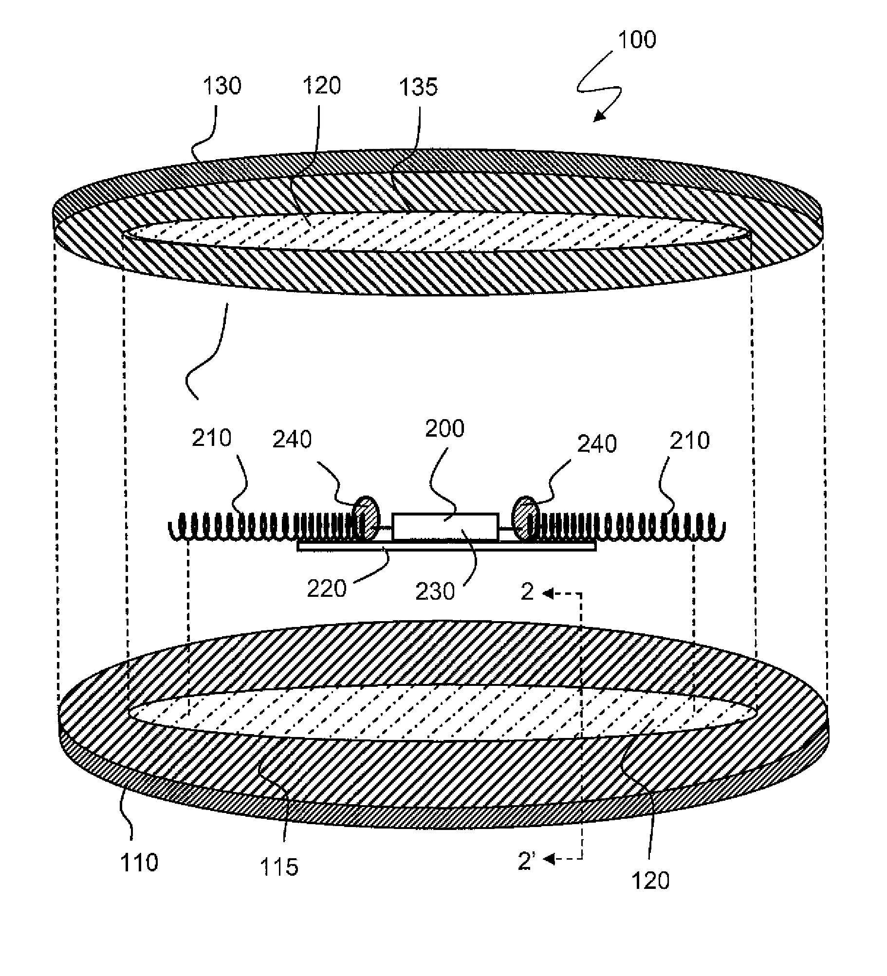
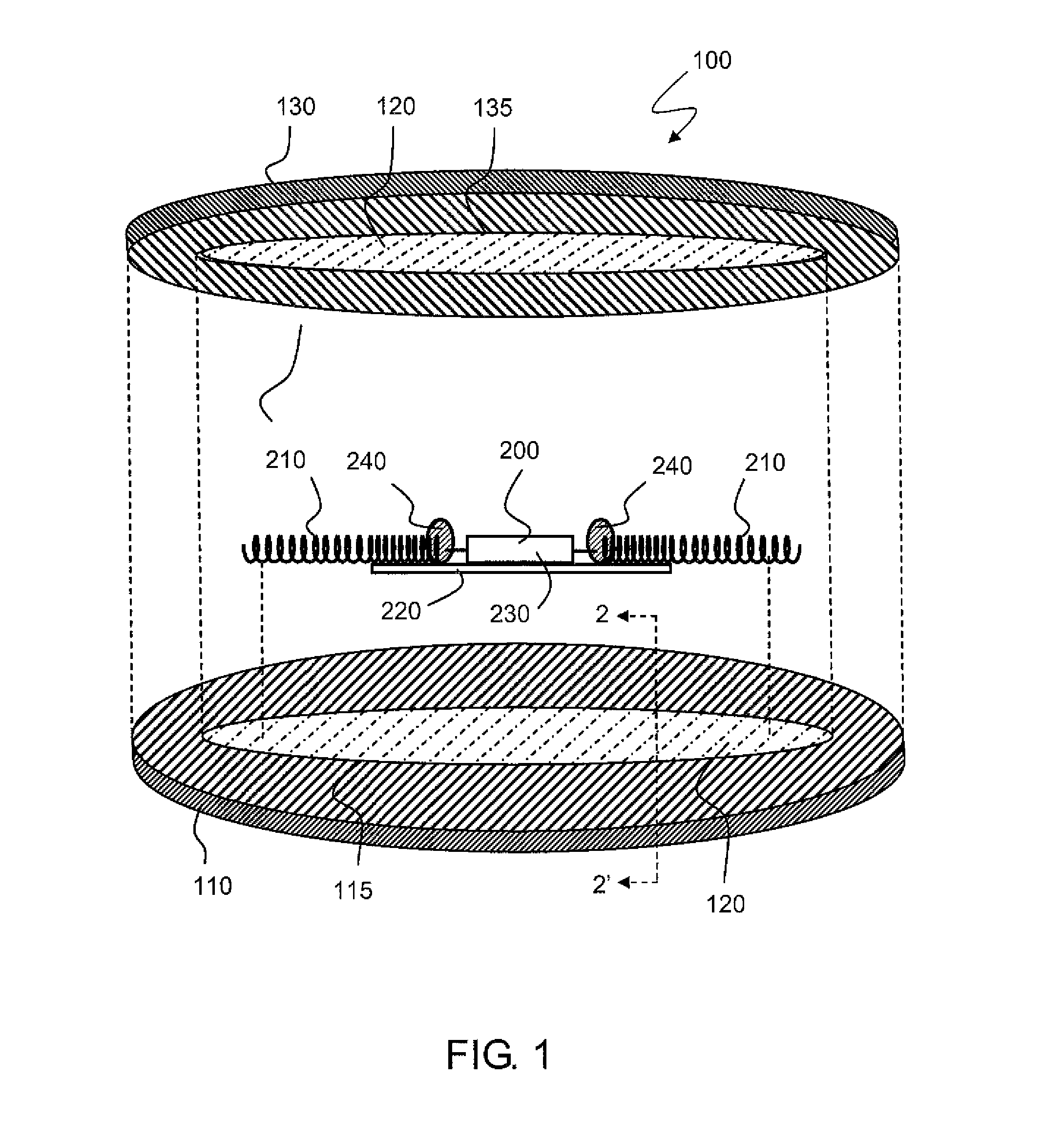
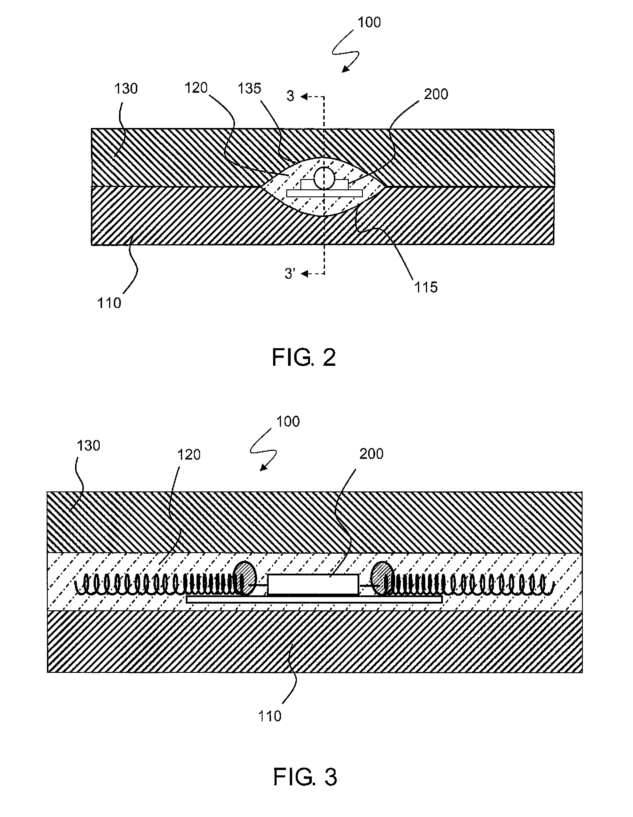
[0019]In general, the present technology is directed to a useful apparatus that can be mounted in a tire structure. The apparatus may be used to secure an RFID tag or other electrical device to the tire structure. The RFID tag or other electrical device is embedded in a flexible middle layer of the tire mountable apparatus to provide many useful advantages, including enhanced mechanical protection and stability.

[0020]Referring to FIGS. 1-3, an exemplary tire mountable apparatus constructed according to one exemplary embodiment of the present invent...


PUM

PropertyMeasurementUnit
viscosityaaaaaaaaaa
viscosityaaaaaaaaaa
densityaaaaaaaaaa

Abstract

A tire mountable apparatus and a method of fabricating a tire mountable apparatus is disclosed. The tire mountable apparatus includes a first layer, a second layer and a middle layer disposed between the first layer and the second layer. The tire mountable apparatus further includes an electrical device embedded in the middle layer of the tire mountable apparatus. The middle layer of the tire mountable apparatus completely surrounds the electrical device and is formed from a potting compound. The potting compound does not require exposure to heat, air, moisture, or light to cure and does not require solvent evaporation or outgassing of reaction products to cure. The tire mountable apparatus may be constructed by curing the potting compound between the first layer and the second layer.

Description

FIELD OF THE INVENTION[0001]The present subject matter relates to a tire mountable apparatus and to a method of manufacturing a tire mountable apparatus. More specifically, the present subject matter relates to a tire mountable apparatus having an RFID tag or other electrical device embedded in a flexible middle layer of the tire mountable apparatus and to a method for constructing the same.BACKGROUND OF THE INVENTION[0002]The incorporation of electrical devices with tire structures has been shown to yield many practical advantages, such as asset tracking and measurement of physical parameters including, for example, temperature and pressure. Many systems utilize radio frequency communication or wireless communication systems between the tire and an external monitoring or interrogating device. Such wireless communication systems often include a RFID tag for communication between an electrical device and the external monitoring or interrogating device.[0003]RFID tags and other electr...

Claims


Application Information

Patent Timeline
Patent Type & Authority Applications(United States)
IPC IPC(8): G06K19/077B29C31/00
CPCB29D2030/0077B60C23/0493B29D30/0061B32B2037/1253B32B38/00B29L2031/3481B32B2038/0076B29L2009/00B29K2105/246B29K2021/00B29D2030/0083B32B37/12
Inventor HOTALING, ELIZABETHSINNETT, JAY CLIFFORD
Owner MICHELIN & CO CIE GEN DES ESTAB MICHELIN
Why Eureka
Try Eureka