Component including two semiconductor elements between which at least two hermetically tightly sealed cavities having different internal pressures are formed and method for manufacturing such a component

Active Publication Date: 2015-12-10
ROBERT BOSCH GMBH
View PDF0 Cites 16 Cited by
  • Summary
  • Abstract
  • Description
  • Claims
  • Application Information

AI Technical Summary

Benefits of technology

[0012]This procedure according to the present invention enables the implementation of multiple, hermetically tightly enclosed cavities between two elements having different defined internal pressures. The internal pressure which has established itself after the bonding process for joining the two elements within the cavities is decreased or increased in a defined way in at least one of the cavities with the aid of a getter material or an outgassing material, this material not being situated in the cavity itself, however, but in an additional cavity. This cavity is connected to the cavity to be influenced via a connecting opening. The internal pressure set in this way is then “frozen” by decoupling the additional cavity having the getter material or the outgassing material. For this purpose, the connecting opening is closed. In this way it is not only prevented that the internal pressure of a cavity changes retroactively due to uncontrolled post-gettering or outgassing, but also that particles of the extraneous material, i.e., of the getter material or of the outgassing material, influence the component functions.
[00

Problems solved by technology

This procedure is problematic for multiple reasons.
This ultimately results in a distortion of the measurement results.
But the micromechanical sensor function is often also inter

Method used


Image

  • Component including two semiconductor elements between which at least two hermetically tightly sealed cavities having different internal pressures are formed and method for manufacturing such a component
  • Component including two semiconductor elements between which at least two hermetically tightly sealed cavities having different internal pressures are formed and method for manufacturing such a component

Examples


Embodiment Construction

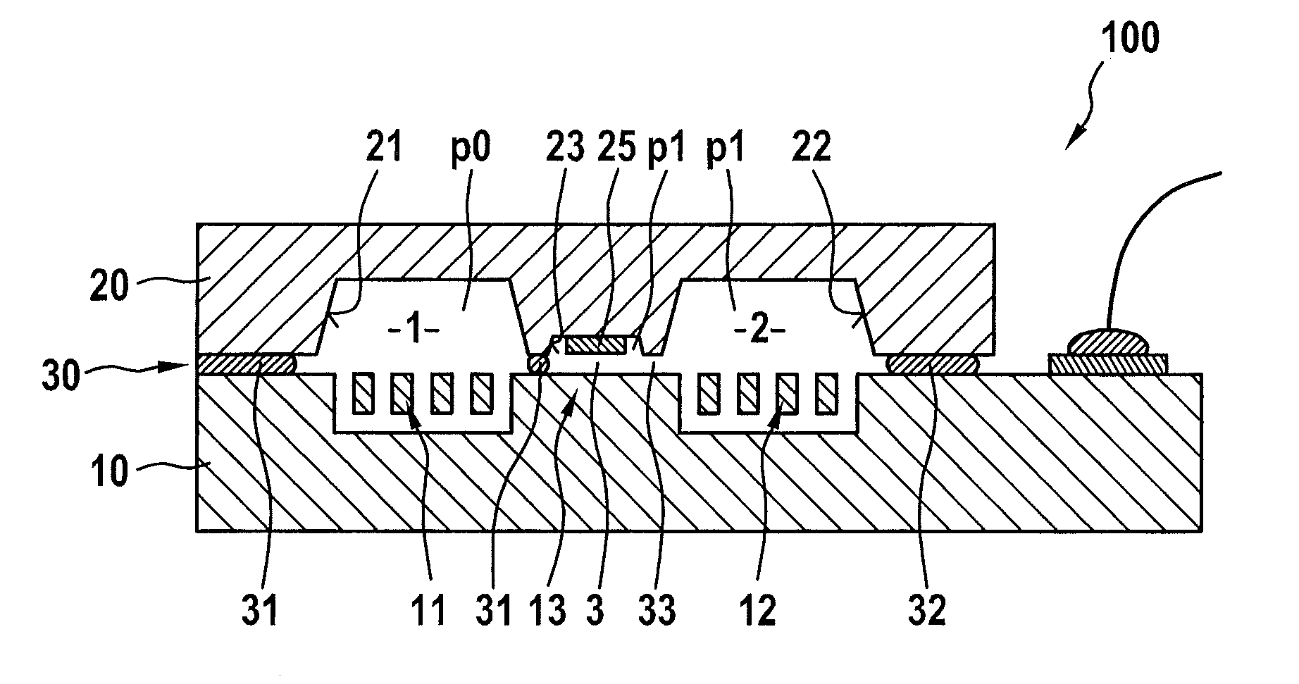
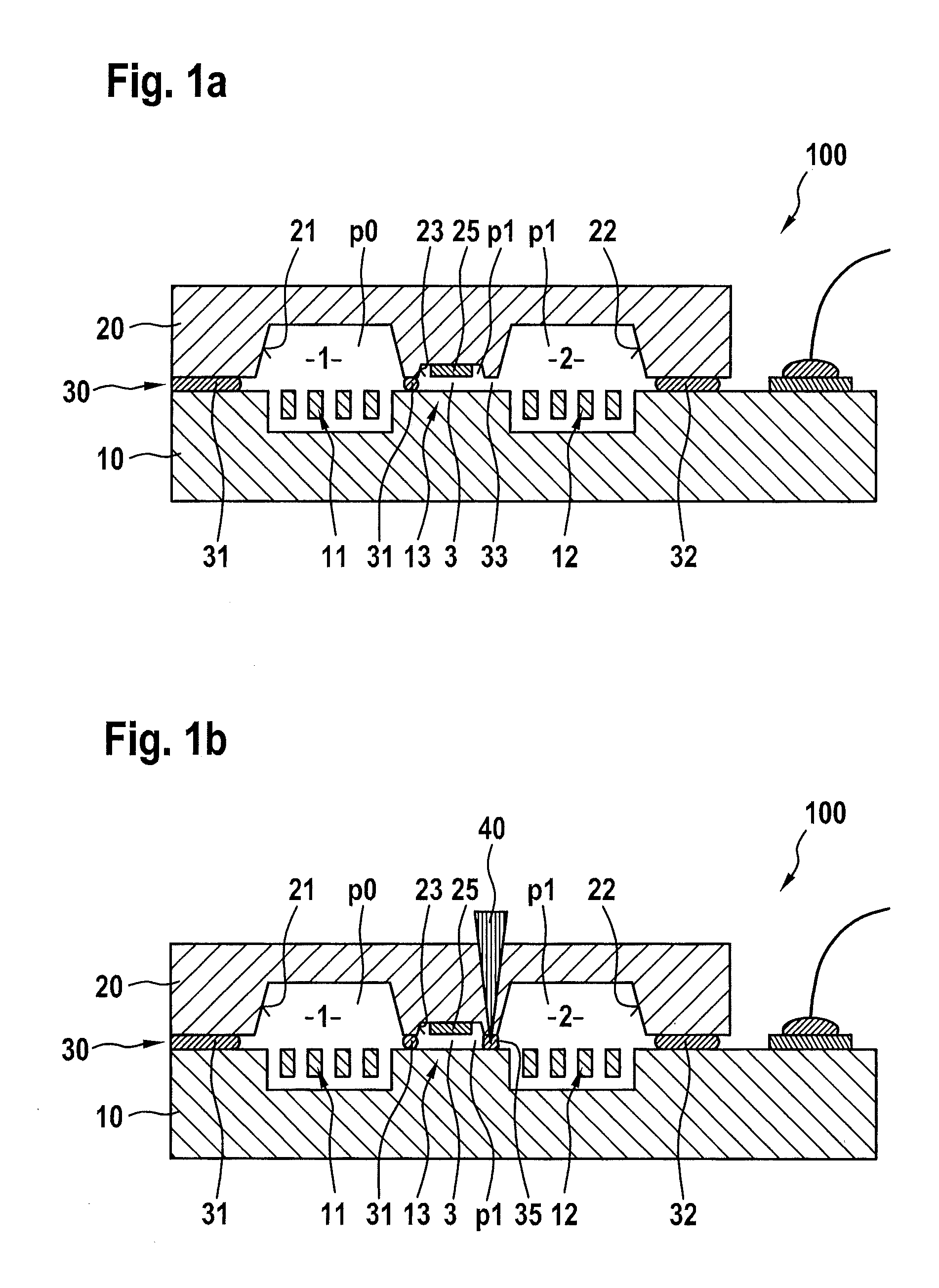
[0020]FIGS. 1a and 1b show the connecting concept according to the present invention with which multiple cavities having different defined internal pressures may be hermetically tightly sealed between two elements of a component.

[0021]Component 100 shown in FIGS. 1a and 1b includes a MEMS element 10, in whose layer structure two micromechanical structures 11 and 12, which are independent from one another, are formed. These may be, for example, sensor structures, such as an acceleration sensor structure and a rotation rate sensor structure, or also micromechanical actuator structures. The two micromechanical structures 11 and 12 are each situated next to one another and also spatially separated from one another by a frame structure 13 in the layer structure.

[0022]A second element 20, which acts as a cap for the two micromechanical structures 11 and 12, is mounted on the layer structure of MEMS element 10. For this purpose, two cap recesses 21 and 22 are formed in the cap bottom side,...


PUM

PropertyMeasurementUnit
Pressureaaaaaaaaaa
Metallic bondaaaaaaaaaa
Internal pressureaaaaaaaaaa

Abstract

For the targeted influencing of the internal pressure within a cavity between two elements of a component, a getter material or an outgassing material is situated in an additional cavity between the two elements. After the two elements are bonded to one another, the additional cavity is still to be joined via a connecting opening to the cavity. The getter material or the outgassing material is then activated so that gasses are bound in the additional cavity and in the connected cavity, or an outgassing takes place. Only when the sought internal pressure has established itself in the connected cavity is the connecting opening to the additional cavity closed. In this way, the getter material or the outgassing material is only used for establishing a defined internal pressure, but no longer has any influence on the internal pressure within the cavity during ongoing operation of the component.

Description

BACKGROUND OF THE INVENTION[0001]1. Field of the Invention[0002]The present invention relates to a component including at least two semiconductor elements which are connected to one another via at least one structured connecting layer, at least two hermetically tightly sealed cavities, in which different defined internal pressures prevail, being formed between these two elements. At least one of those cavities is sealed by a circumferential bonding frame in the connecting layer. Moreover, the present invention relates to a method for manufacturing such a component.[0003]2. Description of the Related Art[0004]One important exemplary application for the components mentioned here are so-called IMUs (inertial measurement units) including a MEMS (microelectromechanical system) element which includes a rotation rate sensor component as well as an acceleration sensor component. The two sensor components are formed in the layer structure of the MEMS element and situated next to one another....

Claims


Application Information

Patent Timeline
IPC IPC(8): B81B7/00B81C1/00
CPCB81B7/0038B81C2203/0145B81B2203/0315B81C1/00285B81B7/02H01L2224/48463H01L21/50H01L23/02H01L23/10
Inventor HEUCK, FRIEDJOFTEBJE, LARSSTAHL, HEIKOGONSKA, JULLIANNEUL, REINHARD
Owner ROBERT BOSCH GMBH
Why Eureka
Try Eureka