Self-retracting hydraulic jack assembly

a hydraulic jack and self-retracting technology, applied in the field of hydraulic jacks, can solve the problems of inconvenient operation, inconvenient maintenance, and large wear and tear of connections, and achieve the effect of convenient operation, reliable and durabl

Inactive Publication Date: 2012-04-19
BLUEROCK TECH +1
View PDF2 Cites 14 Cited by
  • Summary
  • Abstract
  • Description
  • Claims
  • Application Information

AI Technical Summary

Benefits of technology

[0006]One principal object of the present invention is therefore to overcome the deficiencies of prior art jacking devices by providing a self-retracting hydraulic jack assembly that enables full retraction of the jack's telescoping legs with no use of tension springs; reduces the overall number of required mechanical working components; and is more compact, reliable and durable functionally.

Problems solved by technology

While such prior lifting devices have been mildly successful in accomplishing their intended purpose, there are a number of deficiencies in their operation which make them less than satisfactory.
Such connections are subject to extensive wear and tear through repeated manipulation and long-term exposure to adverse weather conditions.
Moreover, such devices are usually quite bulky, unsightly to look at, and offer limited options for mounting the jack due to design constraints.
Jacking devices equipped with a manual rotating crank or hand-operated pump handle are typically quite slow and tedious to operate, and suffer from similar mounting constraints due to the required operational design of the crank or pump, retraction springs, etc.
As noted, numerous working components of such manually operated devices are subject to premature aging and failure due to repeated manual manipulation and exposure to adverse weather conditions, and are bulky and unsightly in appearance.
Particularly in situations where time is of the essence and large load-bearing capacities are required, such deficiencies in the prior art jacking devices can lead to significant and costly downtime, and possible catastrophic failure in the field.

Method used


Image

  • Self-retracting hydraulic jack assembly
  • Self-retracting hydraulic jack assembly
  • Self-retracting hydraulic jack assembly

Examples


Embodiment Construction

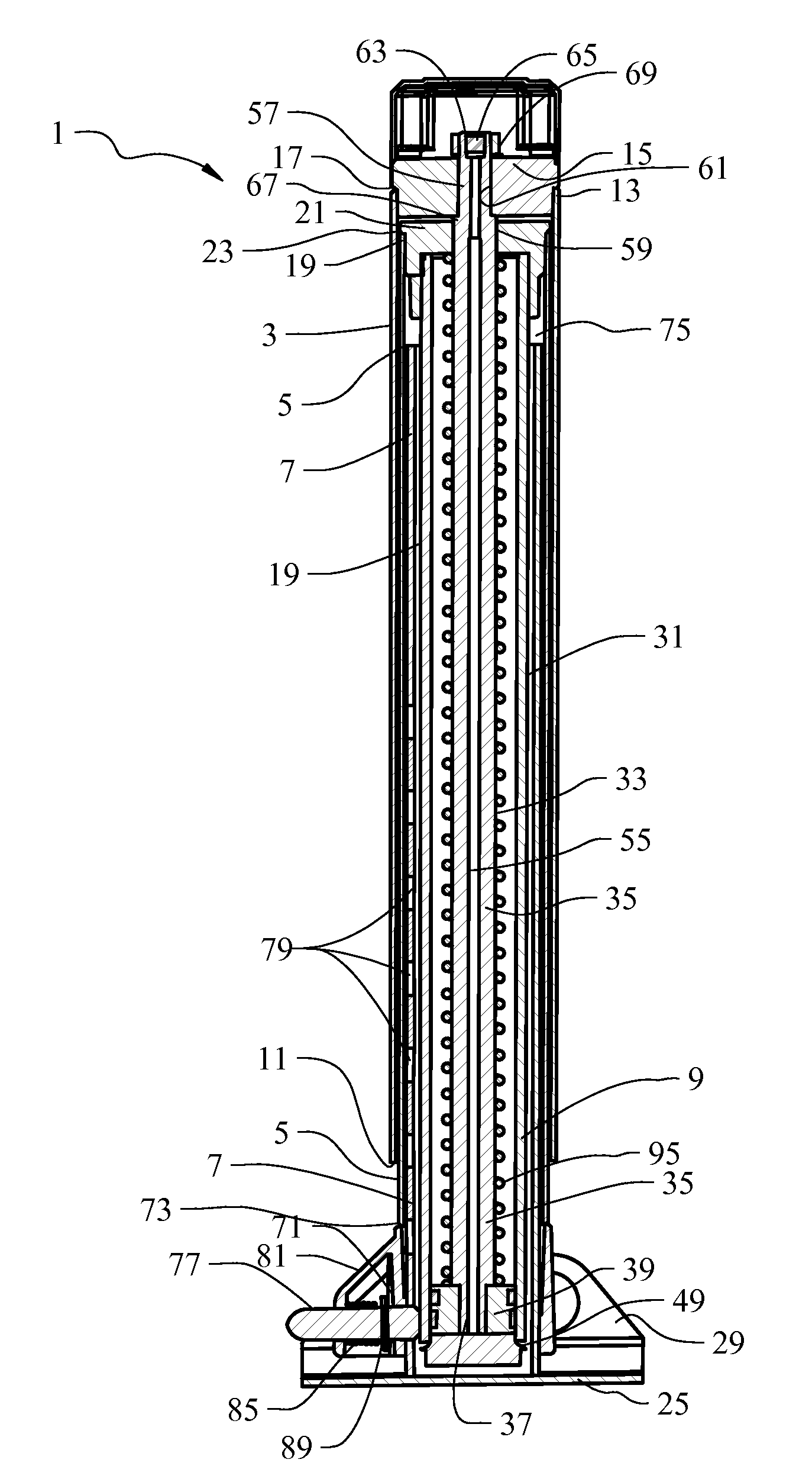
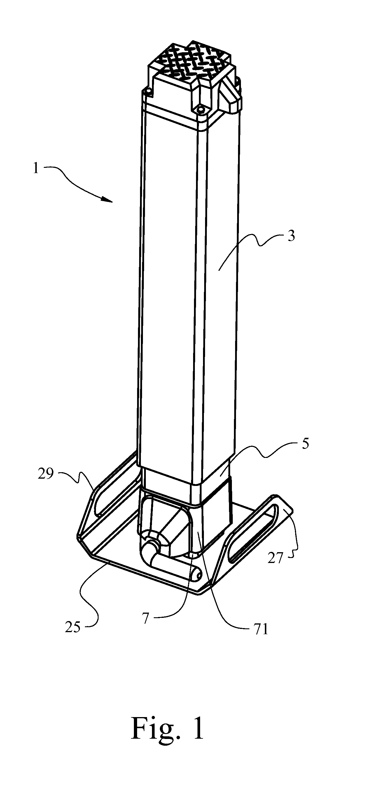
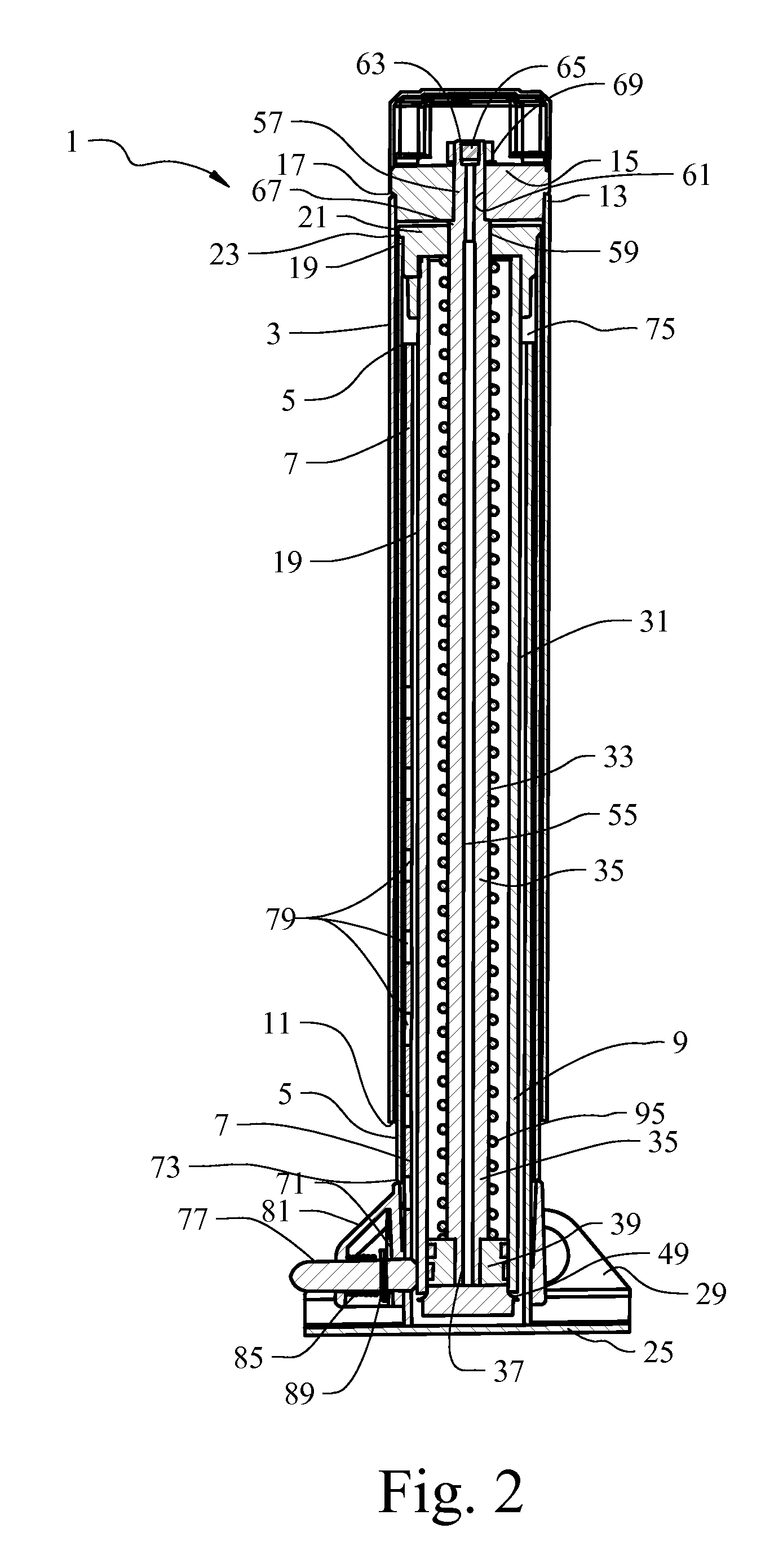
[0020]With reference to FIGS. 1 and 2, a hydraulic jack 1 configured in accordance with the present invention is shown. The hydraulic jack 1 is comprised generally of a plurality of telescoping tubular leg members 3, 5 and 7 that are extensible relative to one another in response to the introduction of hydraulic fluid into an extension cylinder 9. The first tubular leg member 3 constitutes the outer structural body of the jack assembly 1 and provides a mounting surface for attachment of the jack assembly 1 to the tongue of a trailer (not shown) or the like. This outer tubular leg 3 is open at its lower end 11 and includes an upper end 13 to which a bolster end cap 15 is secured. As shown in FIG. 2, the bolster cap 15 is received within the upper end 13 of the outer tubular leg 3 such that the upper end 13 of leg 3 seats against shoulder 17 of bolster cap 15. The bolster cap 15 is then welded to the outer tubular leg 3 at the joint therebetween adjacent shoulder 17.

[0021]As shown, th...


PUM


Abstract

A self-retracting hydraulic jack assembly is provided which includes a leg retraction compression spring carried by the piston rod assembly encased within the hydraulic extension cylinder of the jack. The hydraulic jack has first and second telescoping tubular leg members that are extensible relative to one another in response to the introduction of hydraulic fluid through the piston rod assembly and into the extension cylinder of the jack assembly. A third freely adjustable drop-leg telescopes into the other legs of the jack assembly through a cam actuated pull-pin casting mounted thereto.

Description

BACKGROUND OF THE INVENTION[0001]The present invention relates generally to the art of hydraulic jacks. More particularly, the present invention pertains to hydraulic jack assemblies of virtually any size and capacity with power extension and self-retracting capabilities.[0002]It has heretofore been well known to utilize various mechanical and power-operated support jack assemblies to facilitate coupling and decoupling of a trailer apparatus from a towing vehicle, and as necessary, for supporting and leveling such a trailer. Such jack assemblies are typically mounted upon the tongue of a trailer and oftentimes require manual manipulation to raise and lower the trailer tongue. Manual screw jacks are generally commonplace with smaller load-bearing trailers, where manual rotation of a crank handle turns a vertical screw to effect the lifting and lowering of the trailer's tongue. Other hydraulically powered jacks incorporating a cylinder and ram system are oftentimes utilized for jackin...

Claims


Application Information

Patent Timeline
Patent Type & Authority Applications(United States)
IPC IPC(8): B66F3/25
CPCB60D1/66B66F3/25B60S9/12
Inventor HANSEN, KEVIN J.AHRENHOLTZ, TED E.BOORTZ, JUSTIN PAUL
Owner BLUEROCK TECH
Why Eureka
Try Eureka