Estimation of anisotropy from compressional waves from array sonic waveforms in well logging

an array sonic waveform and anisotropy technology, applied in the field of earth formation investigation, can solve the problems of not taking advantage of the modem tools and technology now available, the anisotropy of shear wave fractures cannot be used to depict the present-day stress regime of fractures, and previous well-logging instruments could only provide data for perpendicular elongation of fractures, etc., to achieve complete and accurate stress history, accurate and complete results, and less cost of operations

Inactive Publication Date: 2012-04-19
GEOBIZ
View PDF6 Cites 11 Cited by
  • Summary
  • Abstract
  • Description
  • Claims
  • Application Information

AI Technical Summary

Benefits of technology

[0025]Up until the present method, the well-logging industry has analyzed data by calculating the fracture from direct azimuth of shear waves. Using this methodology, however, may be misleading and does not take advantage of the modem tools and technology now available in this sector. The present method takes advantage of the sensitivity of modem technology to get a more accurate and complete result. Previous well-logging instruments could only provide data for perpendicular elongation of the fracture—shear wave stress. Innovations in the field, however, can provide data for compressional waves that are more subtle, longitudinal elongations along the matrix. Although the instruments have become more updated, the methodology for analyzing the data has not. Compressional waves have been ignored in well-logging until now.
[0026]As the present method demonstrates, the data from compressional waves should not be dismissed. Shear energy anisotropy only represents the present day stress regime; the present day stress regime may or may not reflect the stress regime that actually caused the fracture. Stress fields change with time as does the direction of the stress applied. Therefore, calculating fracture from a direct azimuth of the shear stress provides an inaccurate stress history of the basin, causing errors in well placement and leading to more costly operations. In contrast, the present method provides a more complete and accurate picture of the stress history of the basin by using compressional anisotropy azimuth. Since the present method leads to more surety in fracture cause, well placement will be more accurate in the field.

Problems solved by technology

Shear wave anisotropy, however, can only be used to depict the present-day stress regime of the fracture.
Unfortunately, the present-day stress regime of the fracture may not coincide with the paleostress regime which actually caused the fracture.
Using this methodology, however, may be misleading and does not take advantage of the modem tools and technology now available in this sector.
Previous well-logging instruments could only provide data for perpendicular elongation of the fracture—shear wave stress.
Although the instruments have become more updated, the methodology for analyzing the data has not.
Therefore, calculating fracture from a direct azimuth of the shear stress provides an inaccurate stress history of the basin, causing errors in well placement and leading to more costly operations.

Method used


Image

  • Estimation of anisotropy from compressional waves from array sonic waveforms in well logging
  • Estimation of anisotropy from compressional waves from array sonic waveforms in well logging
  • Estimation of anisotropy from compressional waves from array sonic waveforms in well logging

Examples


Embodiment Construction

[0032]To further understanding of the present invention, the following discussion is provided. Shear wave energy propagates in a direction perpendicular to the stress motion. When shear waves encounter anisotropic formations, they undergo shear wave “splitting” (the shear wave partitions into two components). Anisotropic formations can be caused by cracks and fractures, for example. The basins caused by these fractures may be indicative of an oil reservoir. As a result, shear wave splitting is used to determine fracture direction to identify the characteristics of the basin.

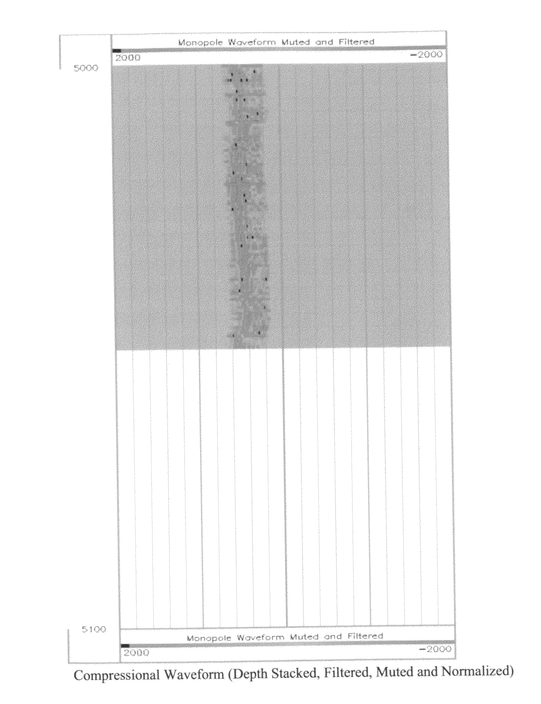
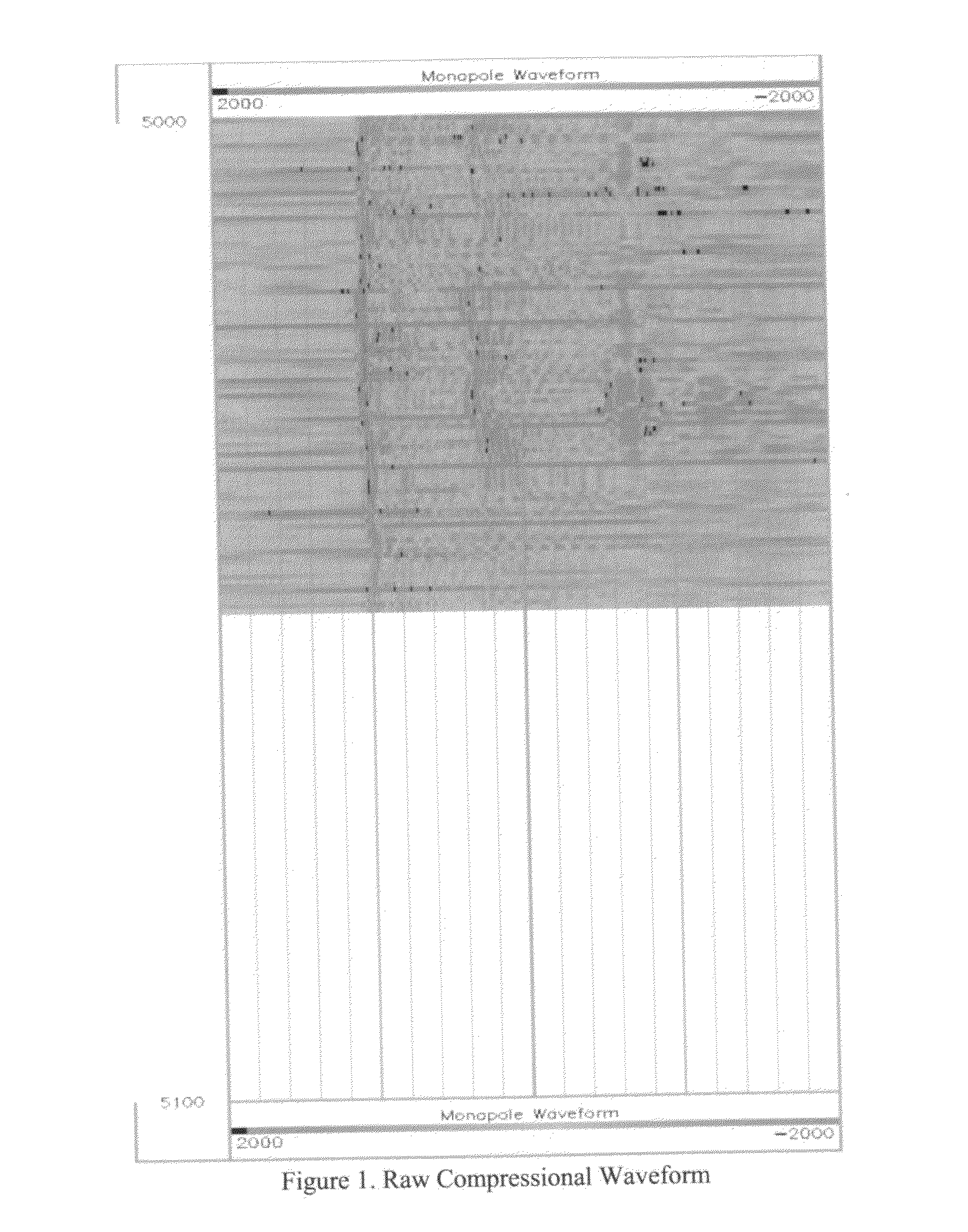
[0033]Moreover, in well-logging, it has been assumed that compressional waves are non-dispersive—that they do not split like shear waves. Compressional wave energy propagates longitudinally along the matrix. Older technologies could not provide accurate data on compressional wave propagation because it results in a subtler disruption. Present day tools, however, can provide accurate data of compressional wave ani...


PUM


Abstract

The present invention provides an improved method for estimating anisotropic formation from wave data using present-day logging tools that allow for the detection of compressional wave splitting to identify fracture direction. This methodology for analyzing compressional waveforms uses the Alford rotation method.

Description

CROSS-REFERENCES TO RELATED PUBLICATIONS[0001]This application claims the earlier filing date of the provisional application filed with provisional patent application No. 61 / 278,481 with date Oct. 21, 2009.[0002]The application also references the following:[0003]1. Leonardon, E G, Logging, sampling and Testing” in Carter, DV (ed): History of Petroleum Engineering, New York City: American Petroleum Institute (1961): 493-578[0004]2. Tsavankin, I., Seismic Signatures and Analysis of Reflection Data in Anisotropic Media, V 29, Elsevier Science Ltd., 2001, pg. vii[0005]3. Alford, R. M, 1986, “Shear Data in the Presence of Azimuthal Anisotropy, Dilley, Texas”, Proceedings of 56th SEG Annual Meeting, p. 476-479FEDERALLY SPONSORED RESEARCH OR DEVELOPMENT[0006]N / AJOINT RESEARCH AGREEMENT[0007]N / ASEQUENCE LISTING[0008]N / ABACKGROUND OF THE INVENTION[0009]1. Field of the Invention[0010]This invention relates to investigation of earth formation and, more particularly, to a method for determinin...

Claims


Application Information

Patent Timeline
Patent Type & Authority Applications(United States)
IPC IPC(8): G01V1/50
CPCG01V2210/586G01V1/50
Inventor BISWAS, SANDIP
Owner GEOBIZ
Why Eureka
Try Eureka