Ultrasound transducer and cooling thereof

a transducer and ultrasonic technology, applied in ultrasound therapy, medical science, therapy, etc., can solve the problems of inefficient transducer heat generation, inability to use standard heat sink structures in blood flow, and considerable heat generated at the transducer

Inactive Publication Date: 2012-04-19
CARDIOSONIC
View PDF31 Cites 41 Cited by
  • Summary
  • Abstract
  • Description
  • Claims
  • Application Information

AI Technical Summary

Benefits of technology

[0007]The present embodiments may provide a transducer which carries out tissue ablation using an unfocused beam from an extended surface of the transducer. The beam heats surrounding fluid and sets up a chimney effect which then serves to cool the transducer surface.

Problems solved by technology

However the transformation of electrical energy into ultrasound is inefficient and considerable heat is generated at the transducer.
The heat needs to be safely dissipated without causing damage to the blood vessel itself, and standard heat sink structures cannot be used in blood flow because heat exchange fins can damage platelets and cause clotting.
Ceramics have low thermal conductivity and thus operation at high power causes relatively large heat differentials across the transducer which often causes cracking.

Method used


Image

  • Ultrasound transducer and cooling thereof
  • Ultrasound transducer and cooling thereof
  • Ultrasound transducer and cooling thereof

Examples


Embodiment Construction

[0075]The present embodiments comprise an ultrasound transducer device and cooling thereof and, more particularly, but not exclusively to the cooling of such a transducer device within a small vessel which may be filled with fluid.

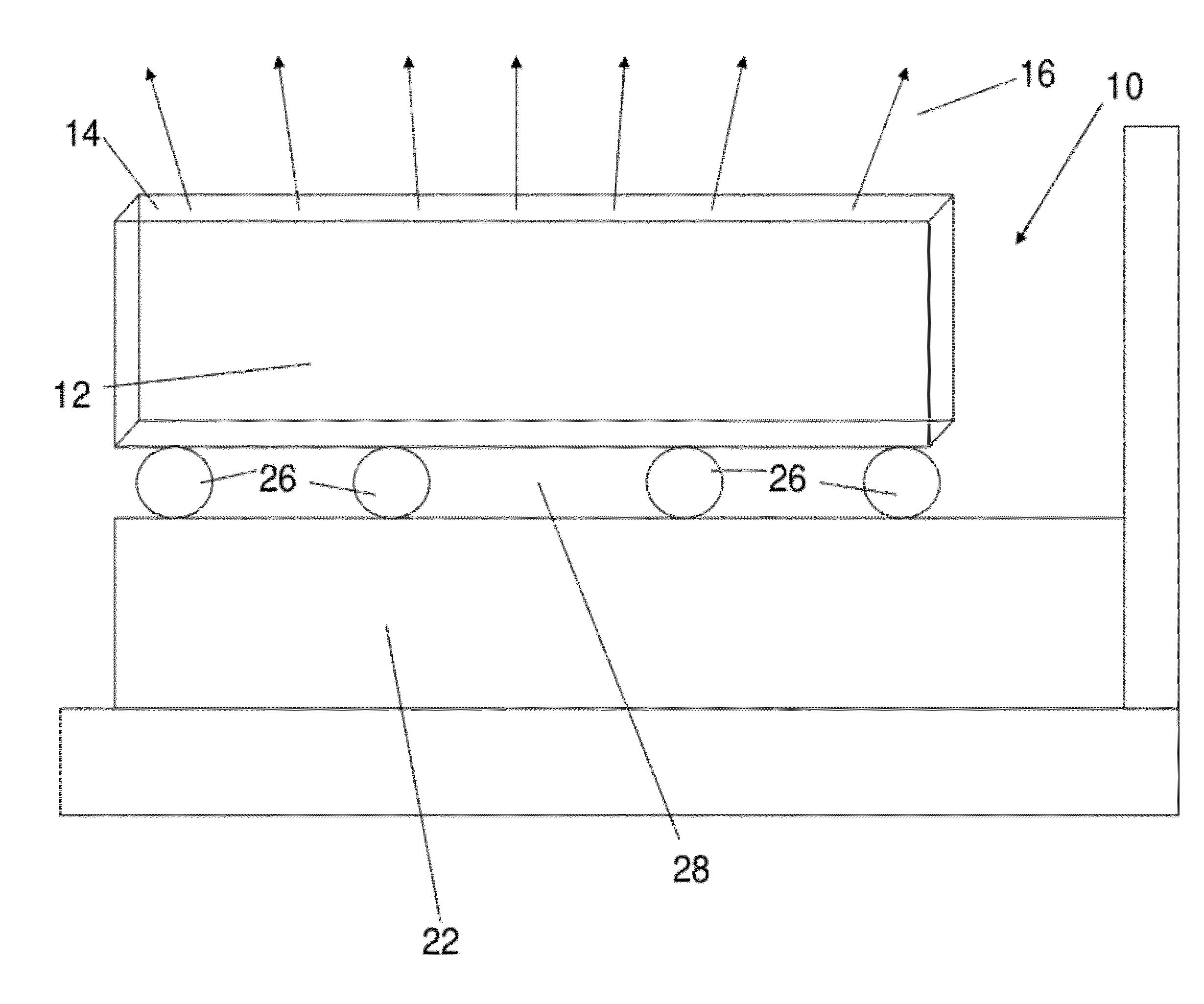
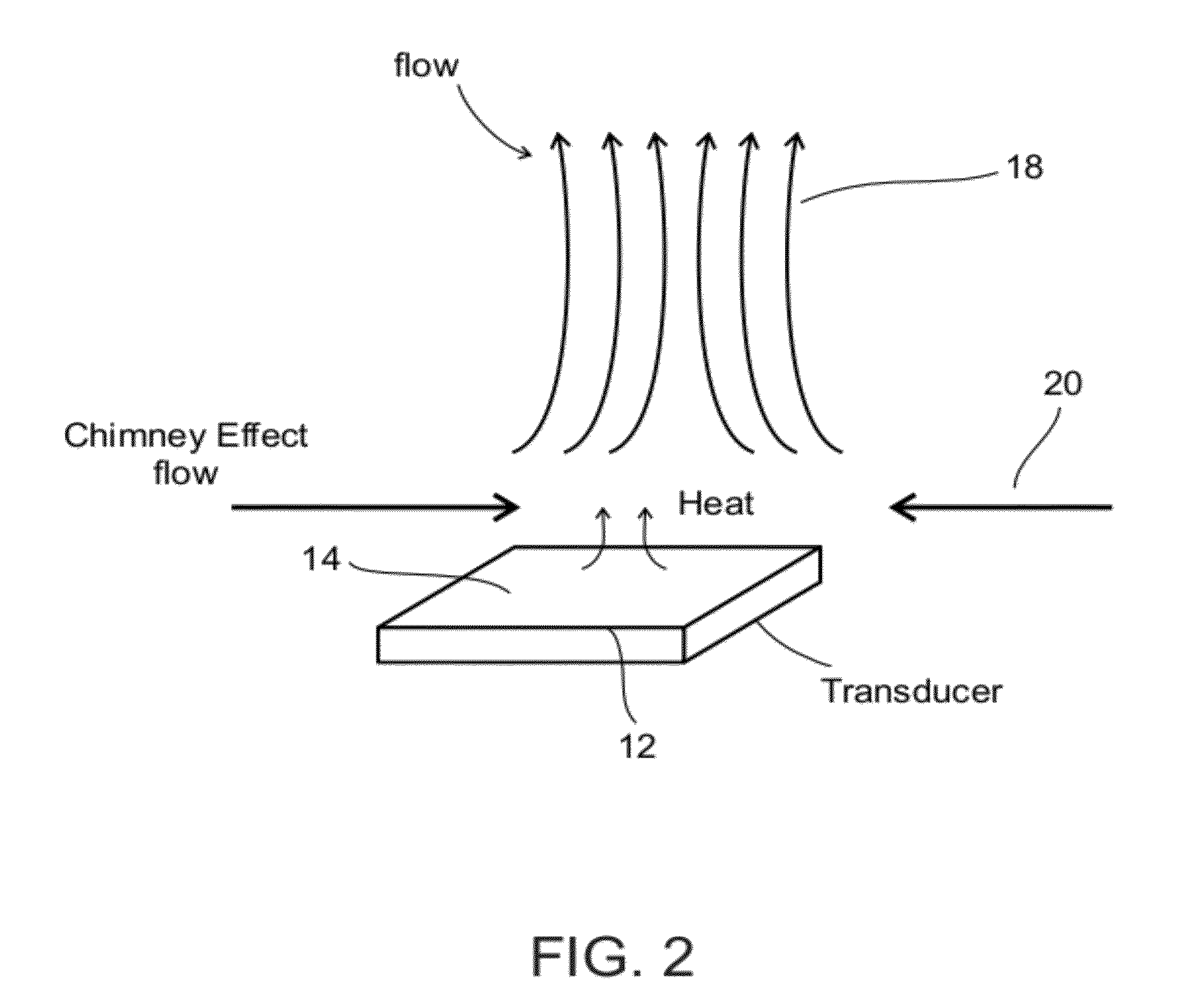
[0076]The present embodiments may provide a transducer which carries out tissue ablation using an ultrasound beam, for example an unfocussed beam produced over the body of the transducer and emanating from an extensive surface of the transducer, as opposed to prior art focused beams which are produced in tightly defined spots. The beam heats surrounding fluid opposite the extensive surface and sets up a chimney effect which provides convective cooling to the transducer extensive surface.

[0077]The transducer may be mounted on a PCB and trenches may be constructed in the PCB for fluid flow to enhance the cooling effect. In addition pumping methods may be used to enhance the flow of liquid around the transducer.

[0078]An embodiment uses an airbacked transducer...


PUM


Abstract

An ultrasonic transducer device for producing ultrasonic beams comprises a body vibratable at ultrasonic frequencies and an extensive surface for beam emanation, the device configured to produce an unfocused, or alternatively a focused, power beam for tissue ablation, the power beam being produced by vibration over the body of the transducer and emanating from the extent of the surface, whereby the extensive surface becomes subject to convective cooling when immersed in a fluid by a chimney effect set up by said unfocused beam.

Description

RELATIONSHIP TO EXISTING APPLICATIONS[0001]This application claims the benefit of priority under 35 USC 119(e) of U.S. Provisional Patent Application No. 61 / 393,947 filed Oct. 18, 2010, the contents of which are incorporated herein by reference in their entirety.FIELD AND BACKGROUND OF THE INVENTION[0002]The present invention relates to an ultrasound transducer device and cooling thereof and, more particularly, but not exclusively to the cooling of such a transducer device within a small vessel which may be filled with fluid, such as a blood vessel or other body lumen.[0003]Sverdlik et al, in PCT / IL2008 / 000234, filed Feb. 21, 2008 disclose a method of using ultrasonic energy for surgical procedures. In a procedure for stabilizing blood vessel wall abnormality, ultrasonic heating is carried out of at least a portion of the blood vessel wall having the abnormality. A parameter is monitored relating to a property of at least a portion of the heated portion of the blood vessel wall; and...

Claims


Application Information

Patent Timeline
Patent Type & Authority Applications(United States)
IPC IPC(8): A61N7/00
CPCA61B17/2202A61B2017/00106A61B2017/22008A61B2017/22051A61B2017/22081A61M37/0092A61N7/022A61N2007/0078A61N7/02A61B17/320068A61B2019/5276A61B2090/378
Inventor SVERDLIK, ARIELSHABTAY, OR
Owner CARDIOSONIC
Why Eureka
Try Eureka