Obstetrical vacuum extractor with over-traction release

a vacuum extractor and vacuum technology, applied in the field of vacuum extractors, can solve problems such as the breaking of the blood vessels connecting the fetal scalp from its underlying surfa

Inactive Publication Date: 2012-04-19
ROSS MICHAEL G
View PDF6 Cites 12 Cited by
  • Summary
  • Abstract
  • Description
  • Claims
  • Application Information

AI Technical Summary

Problems solved by technology

These extractors are often used when spontaneous vaginal delivery is not possible or is unsuccessful.
However, in some situations excessive force has been applied despite the incorporation of a force sensor and / or a slipping mechanism, resulting in the breaking of blood vessels connecting the fetal scalp from its underlying surface.

Method used


Image

  • Obstetrical vacuum extractor with over-traction release
  • Obstetrical vacuum extractor with over-traction release
  • Obstetrical vacuum extractor with over-traction release

Examples


second embodiment

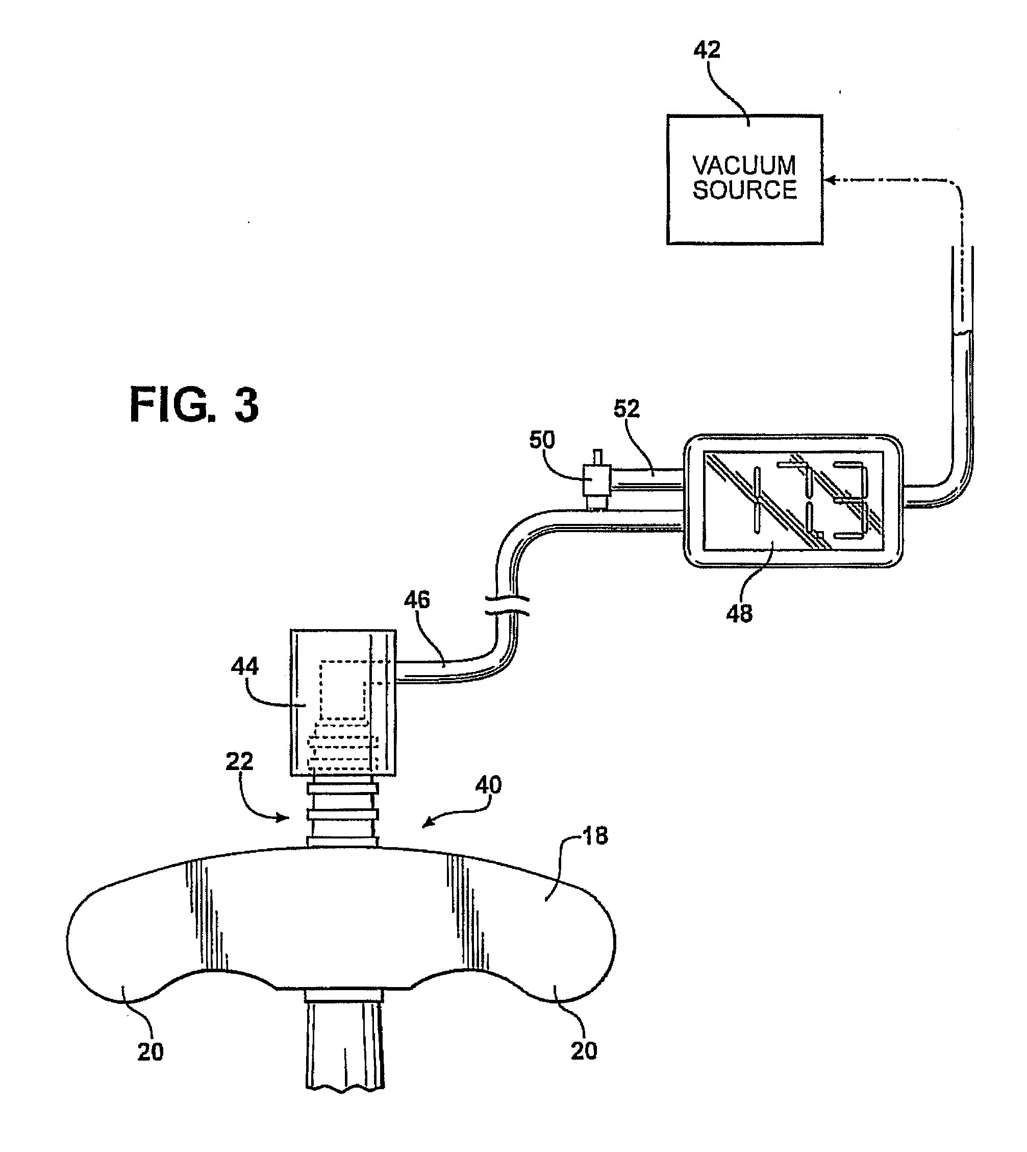
[0045]the invention is illustrated in FIG. 3. The handle end of a vacuum extractor is generally indicated at 40. The vacuum extractor 40 may be identical to the vacuum extractor 10 and to the prior art in that it does not include a gauge 26 or a relief conduit 26; alternatively, in this embodiment of the invention those units are incorporated in the line connecting the vacuum extractor to the vacuum source.

[0046]As illustrated in FIG. 3, the handle 18 of the vacuum extractor 40 is equipped with a vacuum inlet port 22 of the same type as illustrated on the extractor 10 of FIGS. 1 and 2. A vacuum source 42, preferably electrically powered, draws a vacuum through a line 44 which is joined to the connector 22 by a female tubular connector 44 which slides over the male connector 22. Also connected in the line 46 is a digital gauge 48, which is preferably adjustable to a predetermined limit decided on by the attending physician, and a relief valve 50 connected to the gauge by line 52. Whe...

third embodiment

[0070]In the second aspect of the invention, shown in FIGS. 6A and 6B, a vacuum extractor similar to the one shown in FIG. 4B and discussed above is presented. With the exception of handle 130 and handle ears 138, all parts in FIGS. 6A and 6B are the same as those in FIG. 4B. Accordingly, the construction and operation of those parts will not be discussed again. Handle 130 and handle ears 138 may be formed from a suitable plastic of the required mechanical strength and configured so that ears 138 collapse or severely bend when a predetermined fraction force is reached. This would indicate that the vacuum source (not shown) must be immediately disconnected. A typical but none limiting configuration for the handle is presented in FIG. 6A. Here, handle ears 138 of handle 130 are configured to bend or collapse as a result of the narrow constrictions in the region where handle ears 138 join handle housing 158. It should be readily evident to persons skilled in the art that the use of col...

fourth embodiment

[0071]In the second aspect of the invention, shown in FIGS. 7A and 7B, a vacuum extractor 100 similar to the one shown in FIG. 4A, and discussed above is presented. With the exception of a load sensing element 180, shown in FIG. 7B separately and in FIG. 7A as part of vacuum extractor 100, all parts in FIG. 7A are the same as those in FIG. 4A. Accordingly, the construction and operation of those parts will not be discussed again.

[0072]As seen in FIG. 7B, electrical force load sensing element 180 comprises an annular ring member 186 and electrical wires 182, the latter connected to an electrical connector 184. Electrical connector 184 may be connected to an alarm element (not shown), such as a buzzer, or the vacuum source (also not shown) or both. The electronic signal of load sensing element 180 or the circuit to which it is connected, may be activated, at a predetermined over-traction force, to buzz noisily, or to release the vacuum in the vacuum source, or to do both.

[0073]FIG. 7A...


PUM


Abstract

A vacuum extractor for obstetrical use comprises a vacuum cup at one end of an elongated stem having a handle at the opposite end. The vacuum cup is sealed over a portion of the head of the fetus and a vacuum source, usually operating through the stem, connects to the inner side of the cup and secures it to the fetal head. A strain sensor is connected to the stem. When the force applied to the cup through the handle and stem exceeds a predetermined maximum, a valve connecting the vacuum pressure to the atmosphere is opened so as to release the vacuum pressure from the cup. Another extractor comprises an elongated stem and a traction limiter having one or more apertures, a vacuum source connected to a cup supported on the stem, and a handle member in arrangement with the traction limiter operative to open and close the apertures.

Description

CROSS-REFERENCE TO RELATED APPLICATIONS[0001]This application is a continuation-in-part of, and claims priority from, U.S. patent application Ser. No. 12 / 849,291, filed Aug. 3, 2010, which in turn is a continuation-in-part application of, and claims priority from, U.S. patent application Ser. No. 12 / 371,263, filed Feb. 13, 2009, which in turn claims priority from U.S. Provisional Patent Application Ser. No. 61 / 028,243, filed Feb. 13, 2008, all of which are incorporated herein by reference.FIELD OF THE INVENTION[0002]This invention relates to an improved vacuum extractor for childbirth including a vacuum cup connected to a handle through a stem and more particularly to such an extractor including a traction gauge which measures the extraction force applied to the fetus through the cup and releases the vacuum on the cup when the extraction force exceeds a predetermined value.BACKGROUND OF THE INVENTION[0003]Vacuum extractors have long been used as a tool to assist delivery, primarily ...

Claims


Application Information

Patent Timeline
Patent Type & Authority Applications(United States)
IPC IPC(8): A61B17/42
CPCA61B17/442A61B2017/447A61B2017/445
Inventor PORAT, GADIROSS, MICHAEL G.
Owner ROSS MICHAEL G
Why Eureka
Try Eureka