
Monitoring systems and methods for aircraft landing gear

a technology for aircraft landing gear and monitoring systems, which is applied in the direction of testing/monitoring control systems, instruments, force/torque/work measurement apparatus, etc., can solve the problems of not addressing the problem of on-ground operations, landing gear damage, and difficult detection, so as to reduce the average power draw, reduce the difficulty of detection, and prolong the battery life

Active Publication Date: 2012-04-19
THE BF GOODRICH CO
View PDF4 Cites 20 Cited by
  • Summary
  • Abstract
  • Description
  • Claims
  • Application Information

AI Technical Summary

Benefits of technology

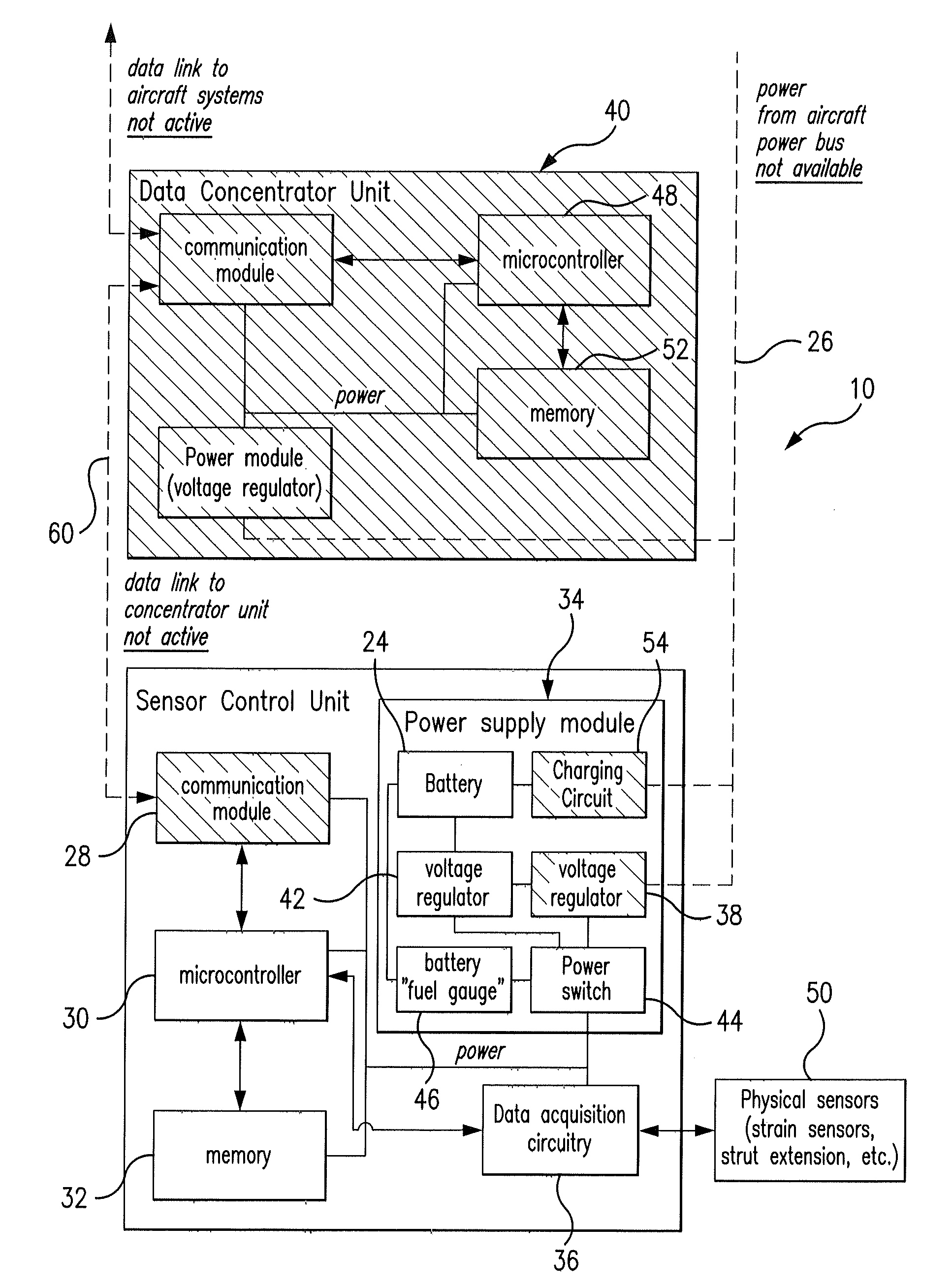
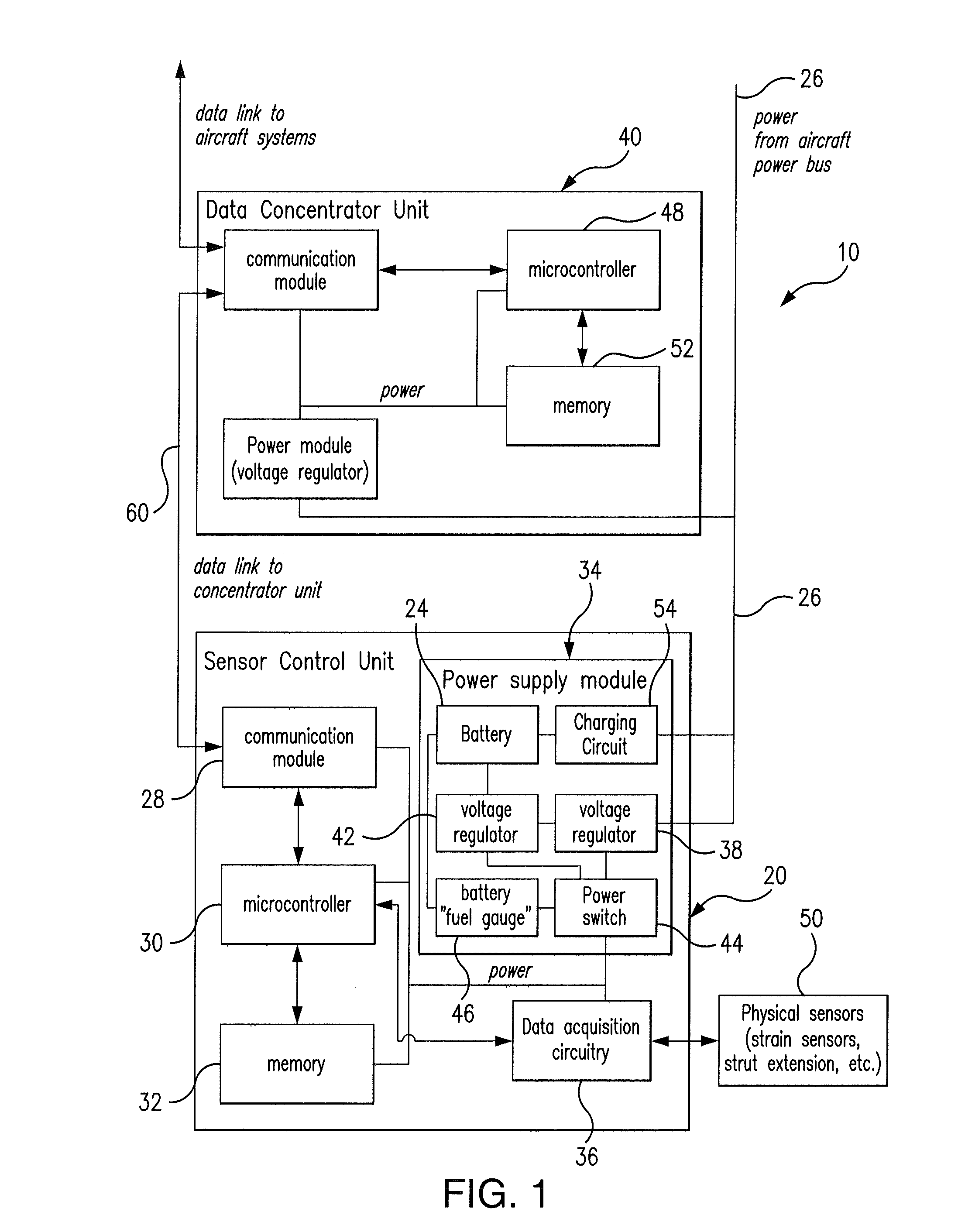
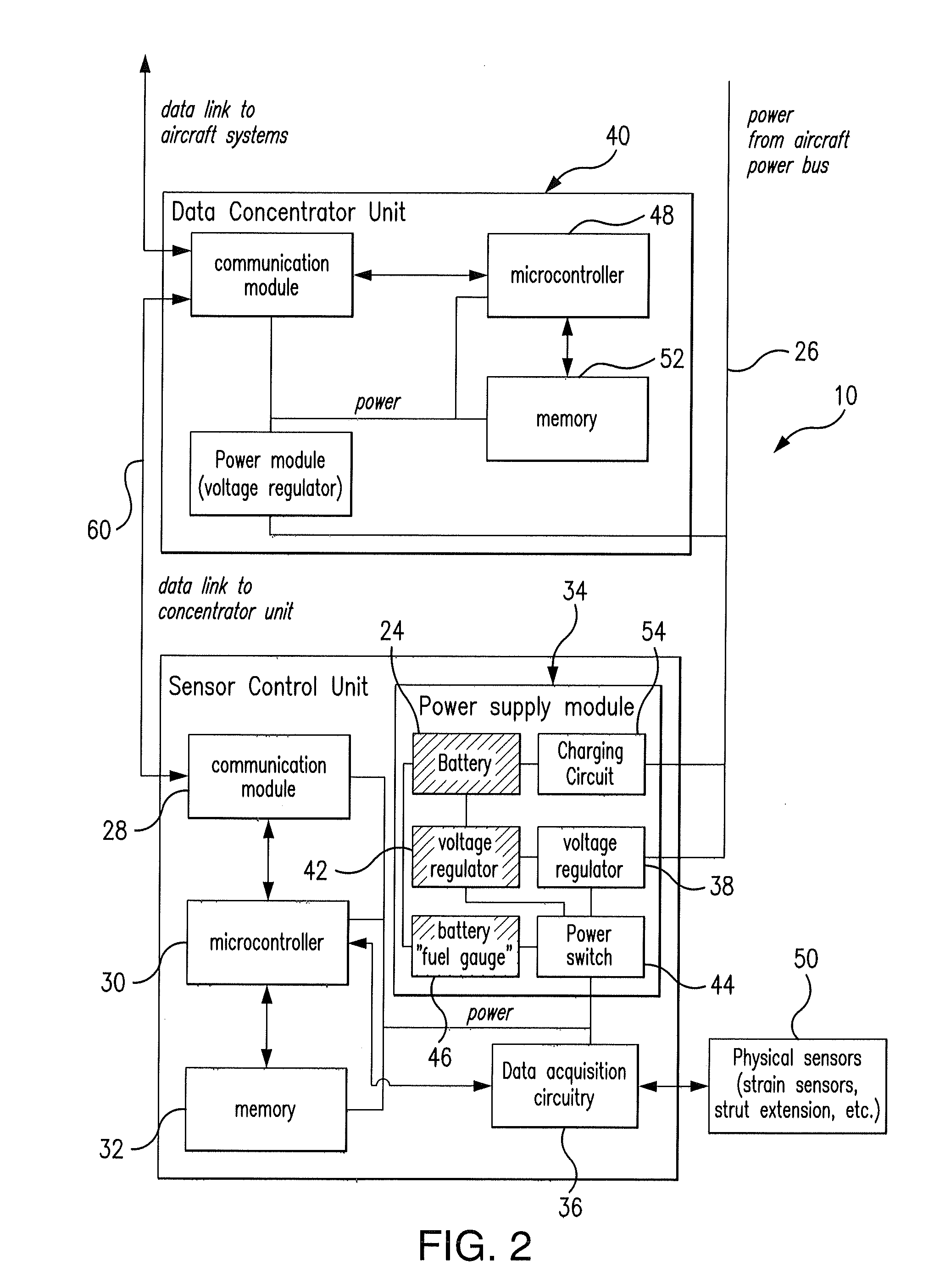
[0015]In preferred embodiments of the present system the system's energy consumption is adjusted by adaptively changing the sensor sampling rate. Sensor data is acquired less frequently when the landing gear status remains unchanged, and the data acquisition frequency is increased if rapid changes are detected in the landing gear status. This allows limiting the average power draw and extending the battery life, thus making the system most useful in scenarios where the aircraft may be powered down and parked for a prolonged period of time.
[0017]The method can further include increasing the sampling rate and / or the data resolution used for the step of interrogating when the strain data or strain vector data exceeds a predetermined threshold. The method of monitoring can further include the step of reducing the sampling rate and / or data resolution used for the step of interrogating when the strain data or strain vector data is below a predetermined threshold. The predetermined threshold can be one of a positive strain threshold, a negative strain threshold, and a rate of change threshold.

Problems solved by technology

Existing or previously proposed landing gear monitoring systems focus on detection of overload conditions due to hard landing events, but do not address the issue of on-ground operations when the aircraft systems may be powered down.
These so called tug-abuse incidents are a leading cause of landing gear damage and are difficult to detect.

Method used


Image

  • Monitoring systems and methods for aircraft landing gear
  • Monitoring systems and methods for aircraft landing gear
  • Monitoring systems and methods for aircraft landing gear

Examples


Embodiment Construction

[0030]Disclosed herein are detailed descriptions of specific embodiments of the systems and methods for monitoring the health and status of aircraft landing gear. It will be understood that the disclosed embodiments are merely examples of ways in which certain aspects of the invention can be implemented and do not represent an exhaustive list of all of the ways the invention may be embodied. Indeed, it will be understood that the systems, devices, and methods described herein may be embodied in various and alternative forms. The figures are not necessarily to scale and some features may be exaggerated or minimized to show details of particular components. Well-known components, materials or methods are not necessarily described in great detail in order to avoid obscuring the present disclosure.

[0031]Figures illustrating the components show some elements that are known and will be recognized by those skilled in the art. The detailed descriptions of such elements are not necessary to ...


PUM


Abstract

A system and method for monitoring loads applied to aircraft landing gear structure. The method includes the step of interrogating at least one sensor positioned proximate the landing gear structure by way of data acquisition circuitry to yield strain data. The method further includes the step of instructing the data acquisition circuitry with respect to a sampling rate and data resolution for interrogation.

Description

CROSS-REFERENCE TO RELATED APPLICATIONS[0001]This application claims benefit of priority from U.S. Provisional Application Ser. No. 61 / 455,170, filed Oct. 15, 2010, U.S. Provisional Application Ser. No. 61 / 455,169, filed Oct. 15, 2010, and U.S. Provisional Application Ser. No. 61 / 393,456, filed Oct. 15, 2010, each of which is incorporated by reference herein in its entirety.BACKGROUND OF THE INVENTION[0002]1. Field of the Invention[0003]The present invention is directed to systems and methods for monitoring the mechanical health and status of aircraft landing gear, and more particularly to systems and methods for monitoring the loads applied to an aircraft's landing gear structure, and still more particularly to landing gear monitoring systems that vary the sensor sampling rate and digital data resolution in order to conserve power during on-ground monitoring when the aircraft's power bus is shut down and a secondary energy source is used to power the monitoring system.[0004]2. Desc...

Claims


Application Information

Patent Timeline
IPC IPC(8): G06F19/00
CPCB64C25/00Y02T50/53B64D2045/008B64D45/0005G05B23/0221G07C5/008G07C5/08Y02T50/50
Inventor ZAKRZEWSKI, RADOSLAW R.LYNCH, MICHAEL A.FUSARE, SCOTT T.HICKS, BRANDONBAIRD, BRADLEY W.
Owner THE BF GOODRICH CO
Learn More