Bogie for guide rail type vehicle

a technology of guide rails and bogies, which is applied in the direction of self-adjusting wheel axles, rail engaging elements, transportation and packaging, etc., can solve the problems of high and complex structure of the switching device, so as to reduce the weight of the turning part, reduce the inertial force generated at the turning part, and reduce the load on the guide wheel from the guide rail

Active Publication Date: 2012-04-26
MITSUBISHI HEAVY IND ENG LTD
View PDF3 Cites 21 Cited by
  • Summary
  • Abstract
  • Description
  • Claims
  • Application Information

AI Technical Summary

Benefits of technology

[0038]In comparison to the bogie disclosed in Non-Patent Document 1, the bogie of the present invention is advantageous in the reduced weight of the turning part. Therefore, the inertial force generated at the turning part can be reduced and the load on the...

Problems solved by technology

The switching device is complex in structure and has many wear components, which requires frequent and time-consuming maintenance.
Thus, the load on the guide wheels is high and the durability of the guide wheels becomes short.
Therefore, the kingpin and the bearing for supporting the kingpin are subject to breakage.
When the kingpin is worn away or when there is misalignment between the kingpin and the bearing, the running stability deteriorates and the height of the guide wheels and the distance between the guide wheels in the lateral direc...

Method used


Image

  • Bogie for guide rail type vehicle
  • Bogie for guide rail type vehicle
  • Bogie for guide rail type vehicle

Examples


first preferred embodiment

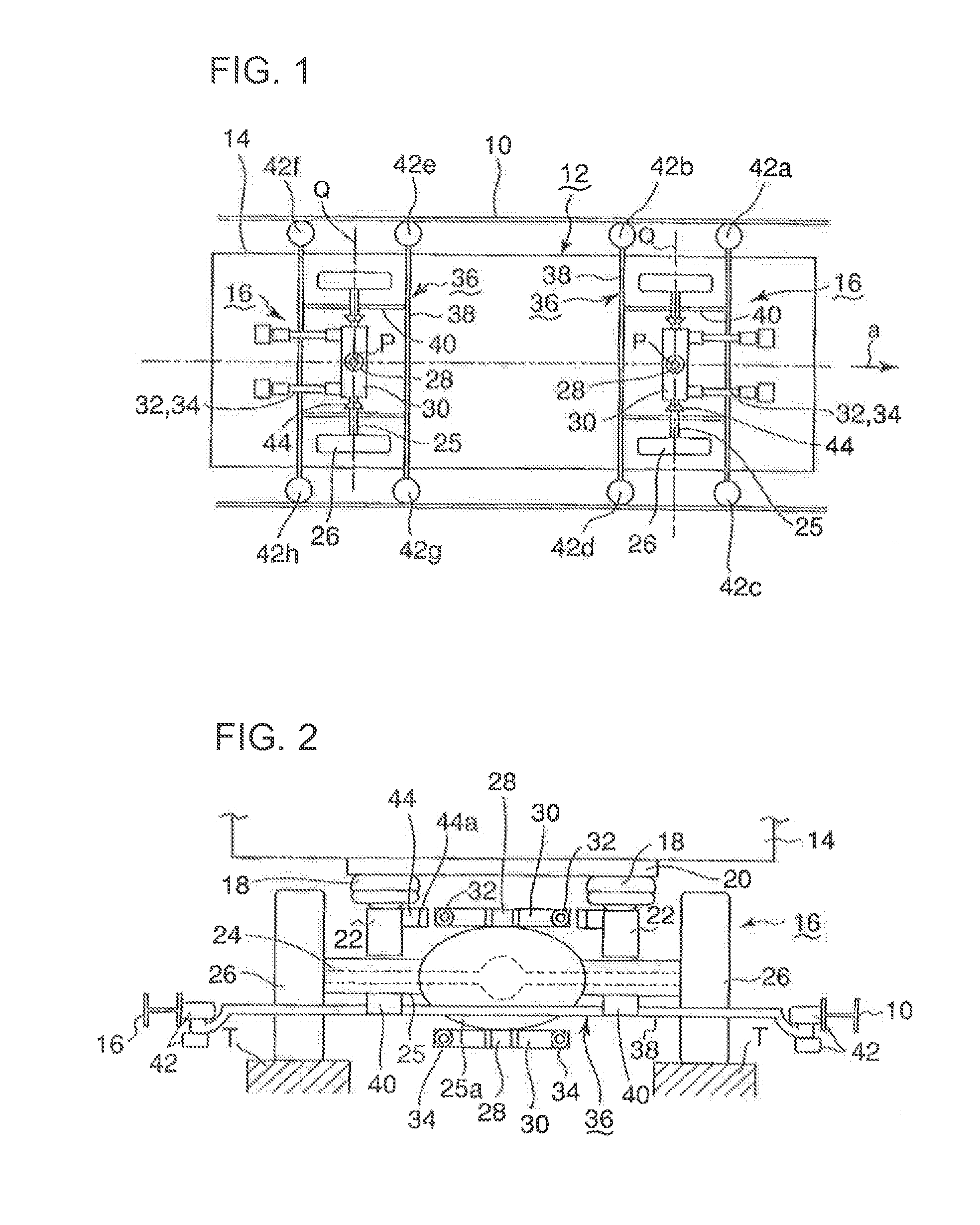
[0049]A vehicle of a guide rail type using bogies of a first preferred embodiment of the present invention will be described in reference to FIG. 1 and FIG. 2. As shown in FIG. 1, in a new transit system, guide rails 10 are disposed along a guideway T on both sides thereof. A vehicle 12 travels along the guideway T. And two bogies 16 are mounted on each vehicle 12 on a front part and rear part thereof. The bogie 16 has eight guide wheels 42a-42h, which rotate along a guide surface of the guide rail 10 (the guide wheels are also indicated as guide wheels 42). The guide wheels 42 guide the vehicle 12 so that the vehicle 12 travels on the guideway T.

[0050]It is also possible to arrange the guide rail in such a manner that one guide rail arranged in a center of the guideway T is interposed between the guide wheels mounted on the bogie from both sides thereof.

[0051]In FIG. 2, the bogie 16 is installed under the vehicle body 14 via air springs 18 for suspension. Specifically, a suspension...

second preferred embodiment

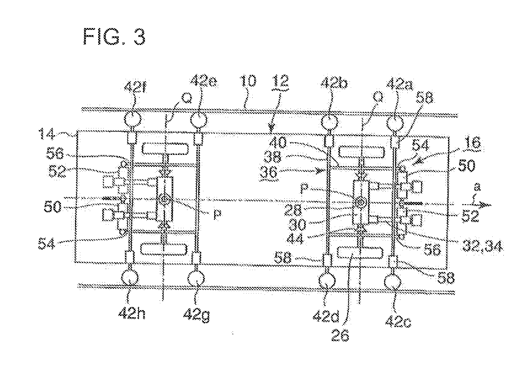
[0066]Next, a second preferred embodiment will be explained in reference to FIG. 3. In. FIG. 3, the structure of the bogie is the same as the first preferred embodiment except for the following. Specifically, the bogie comprises a restoring rod 50 for applying to the guide frame a restoring force that directs the guide wheels in a straight direction, and a turning damper 52 for suppressing a drastic turning movement of the guide frame. The restoring rod 50 and the turning damper 52 are mounted on the traverse bar of the edge side of the vehicle parallel thereto via the connecting rods 54 and 56.

[0067]The restoring rod 50 is structured such that a spring element and a shock-absorbing mechanism of a damping element are connected. The restoring rod applies the force in the direction to restore the guide frame 36 m a neutral position in which the rubber tires 26 are in a straight advancing state. For instance, JP2-210150A shows an example of the rod. The turning damper 52 can be, for in...

third preferred embodiment

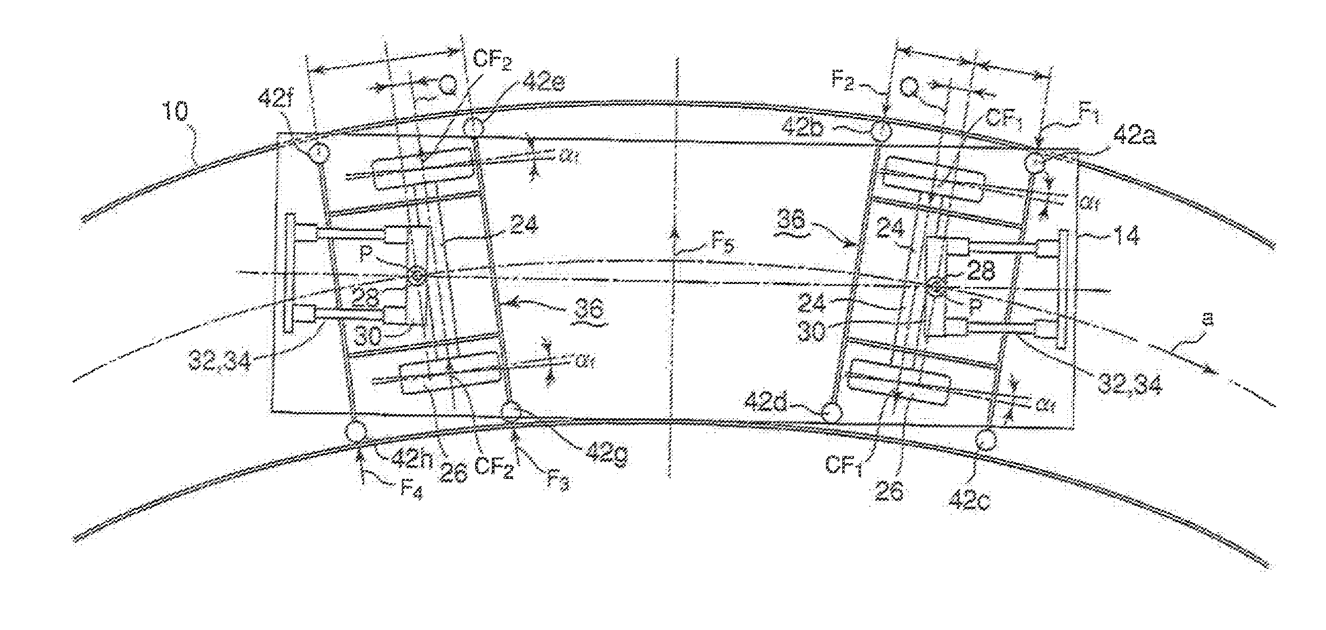
[0072]Next, a third preferred embodiment of the present invention will be described in reference to FIG. 4 and FIG. 5. As illustrated in FIG. 4, a turning center P of the guide frame 36 (the center of the turning pin 28) is displaced by a distance O with respect to a center Q of the drive shaft 24 toward, the edge side of the vehicle body in the front and rear bogies 16 in the traveling direction. The rest of the structure is the same as the first preferred embodiment illustrated in FIG. 1.

[0073]FIG. 5 illustrates the vehicle 12 of the preferred embodiment passing the curved guideway. In FIG. 5, the bogie 16 is subjected to excess centrifugal load F5 which is centrifugal force on the bogie 16 minus the amount reduced by a cant. The turning center P of the guide frame 36 is displaced by the distance O with respect to the center Q of the drive shaft 24 toward the edge aide of the vehicle and thus in the front bogie, the rubber tires 26 is directed to the center line of the guideway by...


PUM


Abstract

A bogie for a vehicle of a guide rail type which is guided by guide wheels that rotate while keeping contact with a guide rail arranged along a guideway of the vehicle, comprises: a guide frame which includes a pair of transverse beams and a connecting member arranged between the pair of the transverse beams, each of the traverse beams being equipped with the guide wheels rotatably on both ends thereof; an axle which is supported on a non-turning part of the bogie such that the axle is capable of turning; and running wheels which are attached to both ends of the axle, wherein the running wheels are rigidly fixed to the axle and the guide frame is fixed to the axle so as to steer the guide frame, the axle and the running wheels integrally.

Description

BACKGROUND OF THE INVENTION[0001]1. Field of the Invention[0002]The present invention relates to a bogie for a guide rail type vehicle in which guide wheels roll along a guide rail while being in contact with the guide rail arranged along a guideway thereof so as to drive the vehicle.[0003]2. Description of the Related Art[0004]A new transportation system as a medium-capacity transportation using rubber tires traveling on a special guideway such as a new transit system and MRT, has become popular in recent years. This transportation system is usually fully automated. In some cases, the transportation system is equipped with guide wheels being guided on a guideway.[0005]As one type of the new transit: system, there is a vehicle which comprises a pair of front guide wheels which are connected to front rubber tires of a front part of the bogie via a steering mechanism and a pair of rear guide wheels being connected to rear rubber tires of a rear part of the bogie via the steering mecha...

Claims


Application Information

Patent Timeline
IPC IPC(8): B61F5/38
CPCB62D1/265B61F5/46B61F9/00B61F13/00
Inventor MAEYAMA, HIROYUKIMITSUI, YOSHINORIKATAHIRA, KOUSUKE
Owner MITSUBISHI HEAVY IND ENG LTD
Why Eureka
Try Eureka