

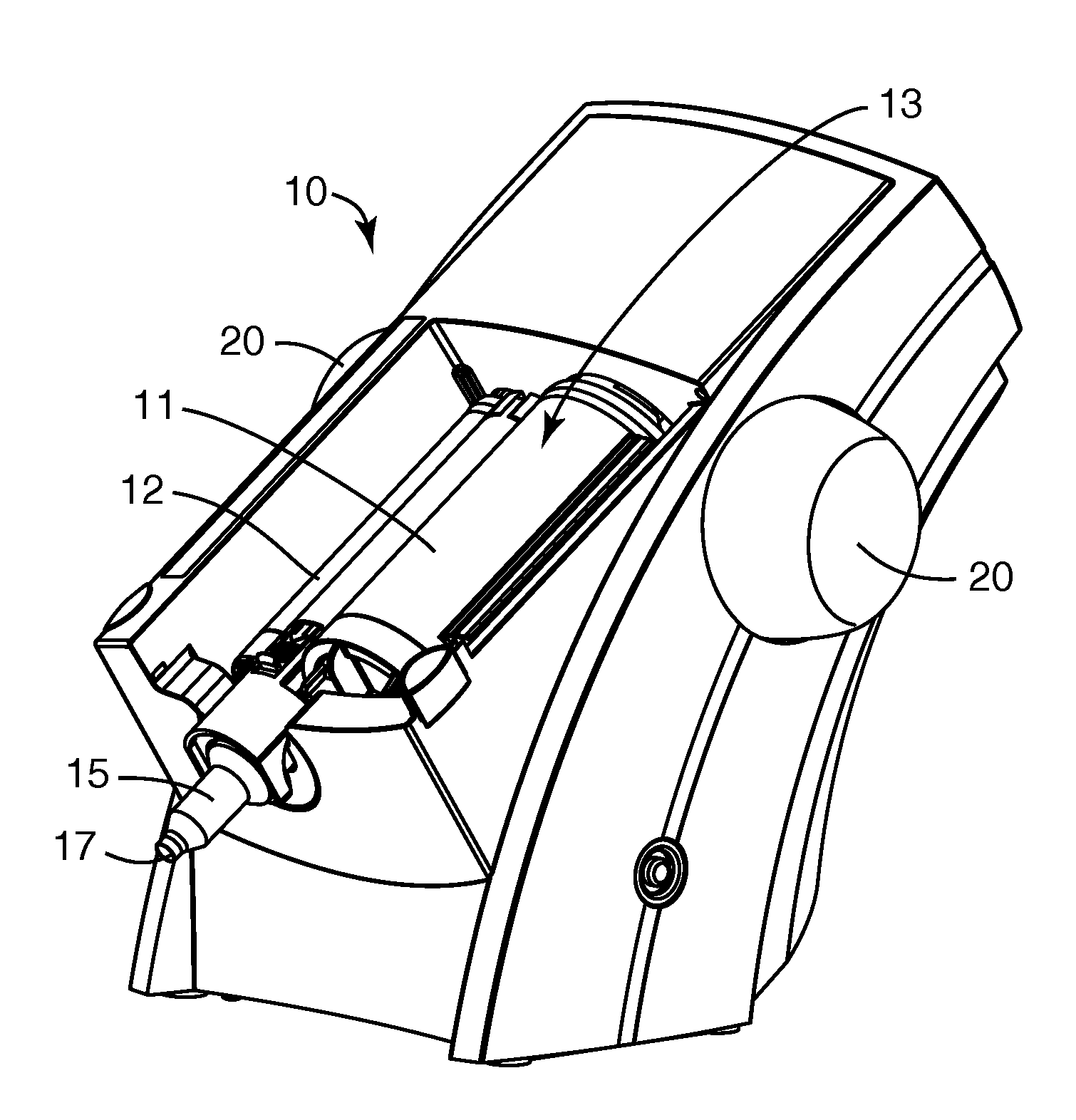
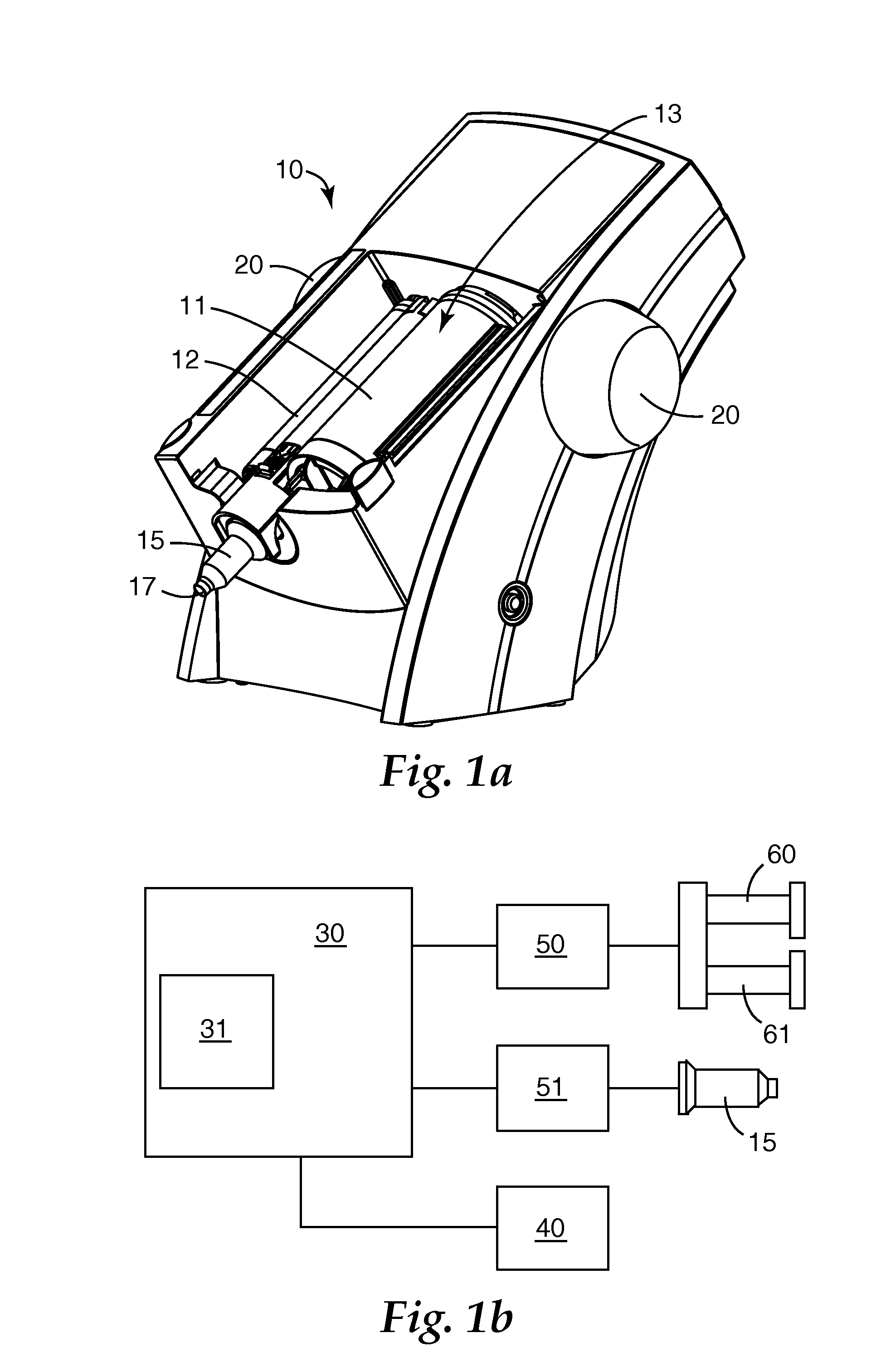
Dispenser and method for dispensing dental material
a technology for dispensing and dental materials, applied in the direction of liquid handling, impression caps, instruments, etc., can solve the problems of increasing resistance, and therefore load, high load applied to driving gearboxes and motors, and difficulty in synchronous advance of driving members, so as to prevent the effect of impression material
- Summary
- Abstract
- Description
- Claims
- Application Information
AI Technical Summary
Benefits of technology
Problems solved by technology
Method used
Image

Examples
example one
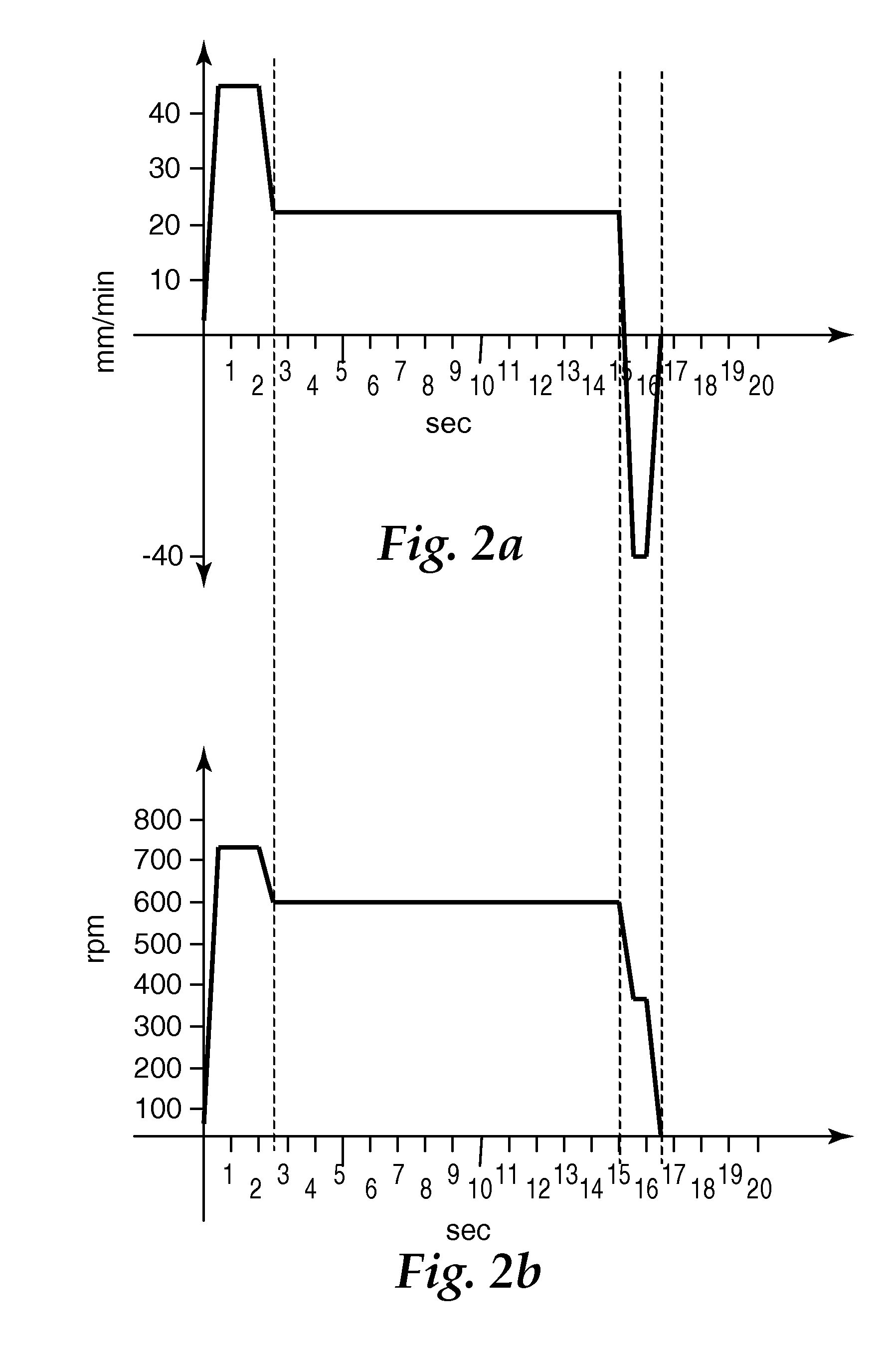
[0112]A device for mixing and dispensing two-component dental impression materials according to the invention having a motor for providing the advancing speed and a separate motor for providing the mixing speed was used in the following manner:
[0113]Drive speed parameters have been devised for a putty viscosity two-component dental impression material, commercially available as Express™ Penta™ from 3M ESPE as in the Comparative Example and stored in the drive controller of the mentioned device.
[0114]A cartridge with two foil bags with the mentioned material as also used for the Comparative Example and fitting with the device of the invention was additionally provided with a chip containing the information used for selecting the drive speed profiles (speed vs. time) devised for this material. The advancing speed profile and the mixing speed profile were as shown in FIGS. 4a and 4b, respectively. The device read the information off the chip on the cartridge.
[0115]The mixing and extrus...
PUM
 Abstract
Description
Claims
Application Information