Clutch and motor

a technology of clutch and motor, which is applied in the direction of wing accessories, couplings, fluid couplings, etc., can solve the problems of high manufacturing cost, large number of components, and complex mechanism of clutch, and achieves long service life and high manufacturing cos

Active Publication Date: 2012-04-26
DENSO CORP
View PDF7 Cites 17 Cited by
  • Summary
  • Abstract
  • Description
  • Claims
  • Application Information

AI Technical Summary

Benefits of technology

[0011]During rotation of the drive side rotation body, the drive side rotation body presses the drive side cam surface in the rotation direction, and the drive side cam surface acts to move the lock member inward in the radial direction and push the lock member against the drive side rotation body. As a result, the lock member is sandwiched between the drive side rotation body and the driven side rotation body to couple the drive side rotation body and the driven side rotation body to be integrally rotatable.

Problems solved by technology

Thus, the clutch has a large number of components and has a complex mechanism.
As a result, facilities for manufacturing the large each of components are necessary, the coupling of such component is burdensome thereby lengthening the time for coupling processes, and the manufacturing cost consequently becomes high.

Method used


Image

  • Clutch and motor
  • Clutch and motor
  • Clutch and motor

Examples


first embodiment

[0023]the present invention will now be described with reference to the drawings.

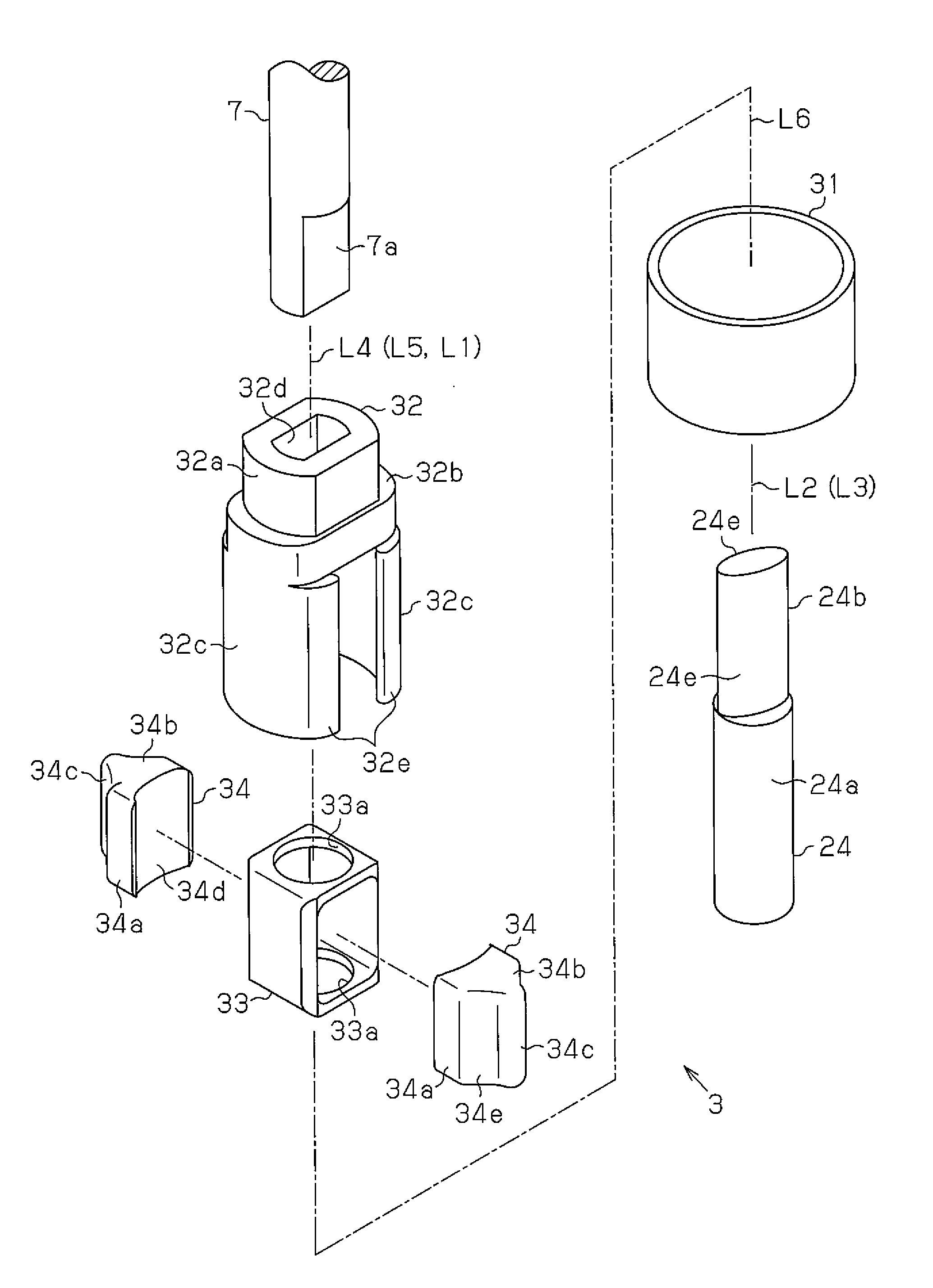
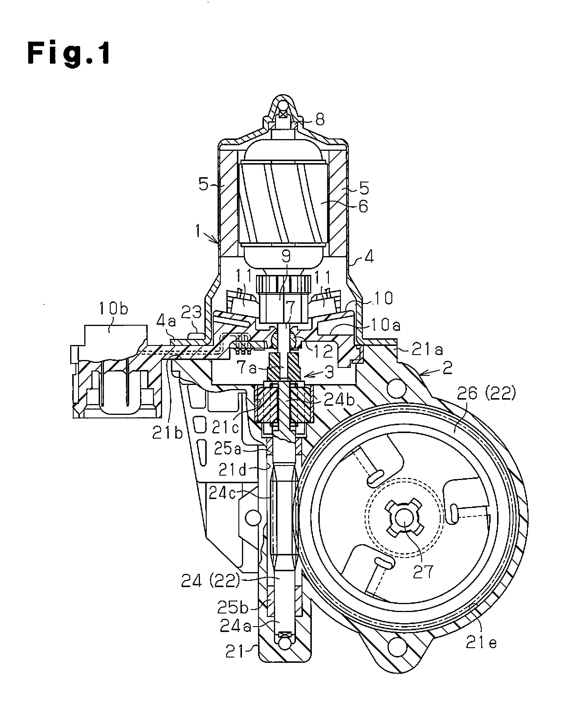
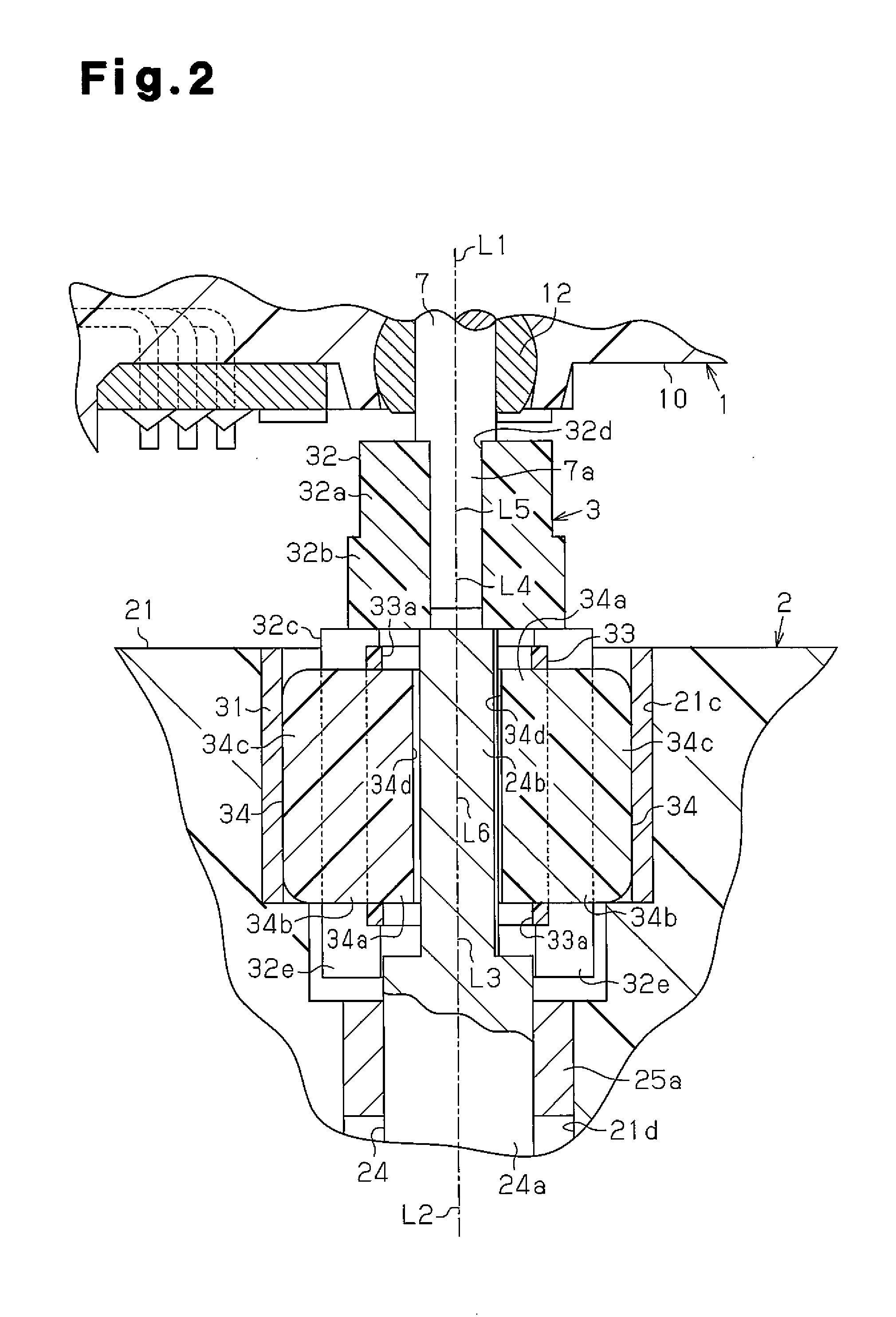
[0024]FIG. 1 is a partial cross-sectional view of a motor of the present embodiment used as a drive source for a power window device. The motor includes a motor unit 1, a deceleration unit 2, and a clutch 3.

[0025]The motor unit 1 has a yoke housing 4, which is tubular and has a closed bottom. A pair of magnets 5 is fixed to the inner circumferential surface of the yoke housing 4 so as to face each other. An armature 6 is arranged on an inner side in a radial direction of the magnet 5 inside the yoke housing 4. The armature 6 includes a rotation shaft 7, that is, a drive shaft extending along an axial direction at the middle in the radial direction of the yoke housing 4. A bearing 8 is arranged at the middle of the bottom of the yoke housing 4. The bearing 8 rotatably supports a basal end of the rotation shaft 7. A cylindrical commutator 9 is fixed to a portion of the rotation shaft 7 closer to a distal ...

second embodiment

[0097]In the second embodiment described above, the support member 53 includes two restriction portions 53c in correspondence with each drive transmission portion 32c. However, one restriction portion 53c may be arranged in correspondence with each drive transmission portion 32c, or three or more may be arranged in correspondence with each drive transmission portion 32c.

[0098]In the first embodiment described above, the lock member 34 is supported by the support member 33, but the support member 33 may be omitted as long as the lock member 34 can move along the radial direction with the rotation of the drive side rotation body 32 and the driven side rotation body 24b. Further, in the clutch 51 of the second embodiment, the support member 53 may be omitted as long as the lock member 34 can move along the radial direction with the rotation of the drive side rotation body 52 and the driven side rotation body 54.

[0099]In each embodiment described above, each lock member 34 includes a p...


PUM


Abstract

A clutch including a drive shaft, drive side rotation body, driven shaft, driven side rotation body, clutch housing, and lock member is disclosed. During non-rotation of the drive side rotation body, when the driven side rotation body is rotated, the lock member is pushed by the driven side rotation body and moved outward in a radial direction thereby bringing the contact portion into contact with the inner circumferential surface of the clutch housing. During rotation of the drive side rotation body, the drive side rotation body pushes a drive side cam surface in the rotation direction, and the drive side cam surface acts to move the lock member inward in the radial direction and push the lock member against the driven side rotation body. Thus, the lock member is sandwiched between the drive side rotation body and the driven side rotation body thereby coupling the drive side rotation body and the driven side rotation body with the lock member to be integrally rotatable.

Description

TECHNICAL FIELD[0001]The present invention relates to a clutch that functions to transmit rotational drive force from a drive shaft to a driven shaft without transmitting rotational force from the driven shaft to the drive shaft and to a motor in which a drive shaft of a motor unit and a deceleration mechanism of a deceleration unit are coupled by the clutch.BACKGROUND ART[0002]A motor used for a drive source of a power window device or the like includes a motor unit, which generates rotational drive force that rotates a rotation shaft (drive shaft), and a deceleration unit, which decelerates the rotation speed of the rotation shaft and outputs the rotational drive force from an output shaft coupled to a load. The rotation shaft arranged in the motor unit and a worm shaft (output shaft) of the deceleration mechanism arranged in the deceleration unit are coupled by a clutch, which functions to transmit the rotational drive force from the rotation shaft to the worm shaft without trans...

Claims


Application Information

Patent Timeline
Patent Type & Authority Applications(United States)
IPC IPC(8): H02K7/112F16D41/06
CPCF16D41/063F16D41/10H02K7/108E05Y2900/55F16D43/02E05F11/505H02K7/1166F16D13/02F16D41/06H02K7/116F16D51/12H02K7/102
Inventor MIZUTANI, NOBUOYAMASHITA, TOMOKI
Owner DENSO CORP
Why Eureka
Try Eureka