Ergonomic Portable Computer

a portable computer and ergonomic technology, applied in the direction of electrical apparatus casings/cabinets/drawers, instruments, couplings, etc., can solve the problems of user neck and upper back strain, increased use difficulty, etc., and achieve enhanced ergonomic function and enhanced working postur

Inactive Publication Date: 2012-04-26
ROGERS DAVID +1
View PDF9 Cites 14 Cited by
  • Summary
  • Abstract
  • Description
  • Claims
  • Application Information

AI Technical Summary

Benefits of technology

[0006]The invention provides a portable computer with a new capability with respect to positioning the computer display screen to fit the needs of an individual user. The novel features of the invention consists of integral mechanisms for elevating and tilting or pivoting the display monitor screen to desired height and viewing angle such that the screen can be adjusted in a vertical direction and can be adjusted in tilt whereby the user can achieve enhanced workin

Problems solved by technology

While these laptop computers and notebook computers offer greater flexibility over desk top computers, they do come with certain inherent problems.
The laptop computers and notebook computers keyboards are relatively small and make it more difficult for the user to use over an extended period of time due to the often poor posture caused by the positioning of the hands/wrists on the small keyboard and the relatively lower position display monitor.
With

Method used


Image

  • Ergonomic Portable Computer
  • Ergonomic Portable Computer
  • Ergonomic Portable Computer

Examples


first embodiment

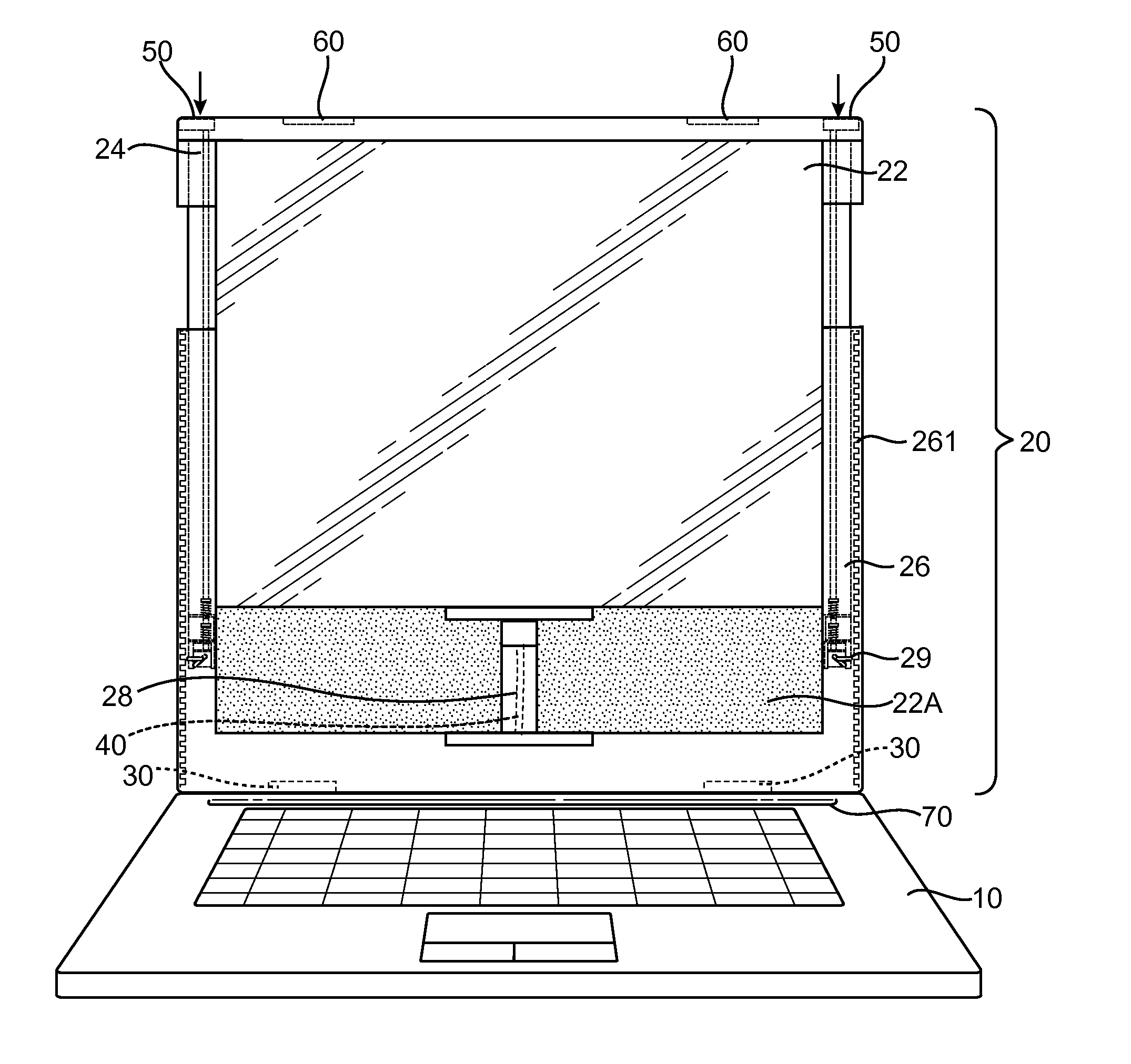
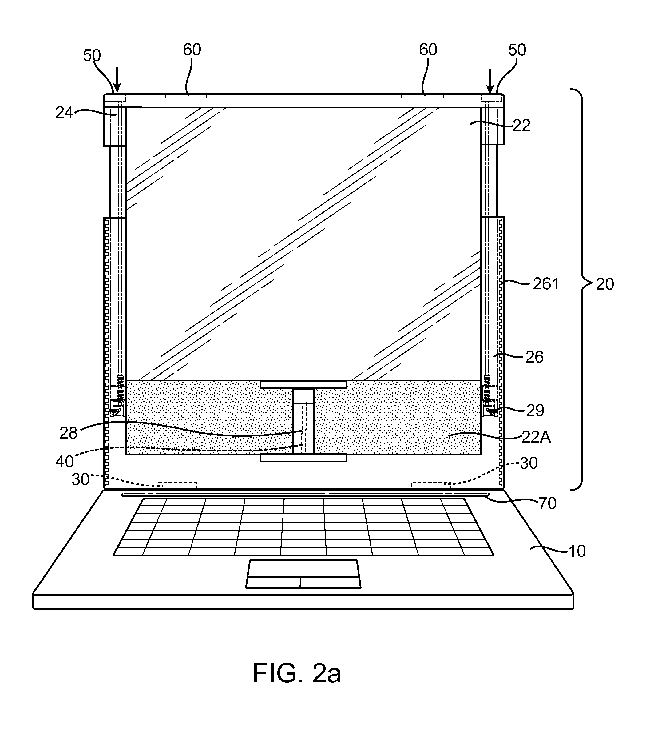
[0028]In the invention, located on an inner wall on each side of the base panel within the channel of the frame of the base panel is a plurality of slots to form a vertical rack 261. FIG. 5c illustrates a vertical rack 261 on the right side of the base panel. A similar vertical rack is also present on the left side of the base panel. A pair of user operable press buttons 50 are located along the top edge of the display unit, one on each end of the top edge. As illustrated in FIGS. 5c and 5d, each of the press buttons is operably connected to a push rod 35. The push rod 35 is adjacent to the outer edge of the interior panel 24. Referring to FIG. 6a, a compression spring 34 is located along the push rod. At the bottom of the push rod is a mobile housing assembly 33 consisting of a recess or cavity 32. Situated within the cavity is a cross pin 31. The cross pin is perpendicularly connected to a locking pin 29 in a T formation. The cross pin resides within the recess 32 of the mobile ho...

second embodiment

[0031]the invention comprises a spring loaded pivotable locking mechanism. Details of this embodiment will be explained in reference to FIGS. 9a and 9b. The user operable press buttons 50 as described in FIG. 1 are each connected to a push rod 80 as shown in FIGS. 9a and 9b. On each side of the base panel 26, contained within the channel 84 forming the frame for the base panel, is a spring loaded pivotable locking mechanism 81. At the center of the locking mechanism is a connecting means 82 for attaching the pivotable locking mechanism to an interior wall of channel 84. In a resting position, an outer most edge of the locking mechanism 81 rests firmly against interior panel 24 such that the interior panel 24 and display panel 22 are secured in place and cannot travel vertically upward or downward. In order to elevate the display panel 22 and the interior panel 24, the user would depress the press buttons 50 on both sides simultaneously so as to trigger the push rod 80 to travel down...


PUM


Abstract

A portable computer with ergonomic features comprises a height adjusting mechanism and a tilt adjusting mechanism for elevating the computer to a preferred viewing height and adjusting the viewing angle for an individual user.

Description

RELATED APPLICATION[0001]This application claims the benefit under 35 U.S.C. §119 (e) of U.S. Provisional Patent Application No. 61 / 366,723 filed Jul. 22, 2010.FIELD OF THE INVENTION[0002]The present invention relates generally to ergonomic portable computers and more specifically, it relates to laptop computers and notebook computers with an ergonomic design for positioning the monitor to a comfortable viewing position for the user so as to reduce the probability of physical injury brought on by inappropriate position of computer monitors for extended periods.BACKGROUND OF THE INVENTION[0003]Over the last decade, use of computers has increased dramatically with the introduction of laptop computers and netbook computers. Laptop computers and netbook computers are designed to be compact and generally weigh significantly less than desk top computers to enable the portability of the computer. The design of laptop computers and notebook computers generally consists of a small display mo...

Claims


Application Information

Patent Timeline
IPC IPC(8): H05K7/00F16B17/00
CPCY10T403/602G06F1/1637
Inventor ROGERS, DAVIDMITHAIWALA, FARIDA
Owner ROGERS DAVID
Why Eureka
Try Eureka