
Diagnostic system and method for monitoring operating conditions of components of a turbine machine

Active Publication Date: 2012-04-26
SIEMENS ENERGY INC
View PDF2 Cites 16 Cited by
  • Summary
  • Abstract
  • Description
  • Claims
  • Application Information

AI Technical Summary

Problems solved by technology

However, even superalloy materials are not able to withstand extended exposure to the hot combustion gas of a current generation gas turbine engine without some form of cooling and / or thermal insulation.
Such real world operating environment data is very difficult to obtain, particularly for components that move during the operation of the engine, such as the rotating blades of the turbine.
Despite the extreme sophistication of modern turbine engines, such as gas turbines for generating electrical power or aircraft engines for commercial and military use, designers and operators have very little information regarding the internal status of the turbine engine components during operation.
This is due to the harsh operating conditions, which have prevented the use of traditional sensors for collecting reliable information of critical engine components.
While improved engine design and usage of materials with high temperature capabilities provide solutions for fuel efficiency and performance, reliability issues remain.
This complicates the introduction of sensors to monitor the real-time condition of the components, including critical elements such as rotating disks and blades.
Disks and rotors are expensive and long lead time turbine components.
The modifications can often lead to reductions in rotor life of several orders of magnitude.
Changing a rotor costs millions of dollars, and requires that a turbine engine be fully disassembled, requiring an outage that may be more than a month long.
A power company will typically lose about one million dollars per day when a turbine is not generating electricity.
For this reason, long outages are not desirable.
However, without local calibration, the sensitivity and accuracy of such surface measurement techniques is not sufficient.
However, such systems provide information for only the point location where they reside, and only for the component on which they are located.

Method used


Image

  • Diagnostic system and method for monitoring operating conditions of components of a turbine machine
  • Diagnostic system and method for monitoring operating conditions of components of a turbine machine
  • Diagnostic system and method for monitoring operating conditions of components of a turbine machine

Examples


Embodiment Construction

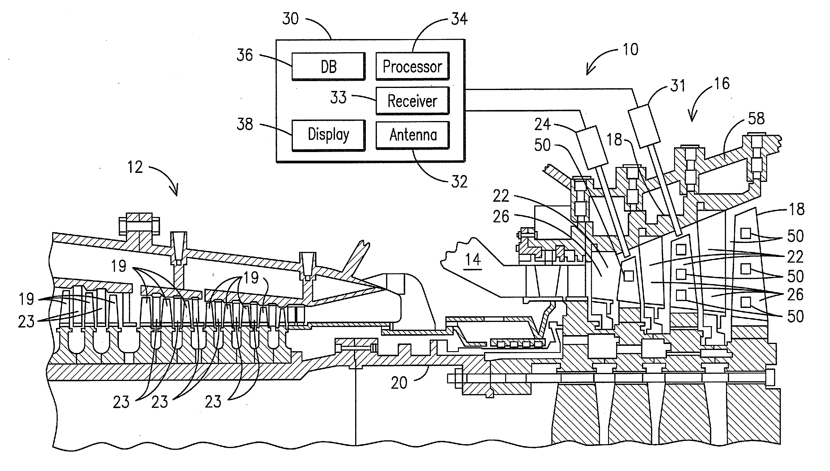
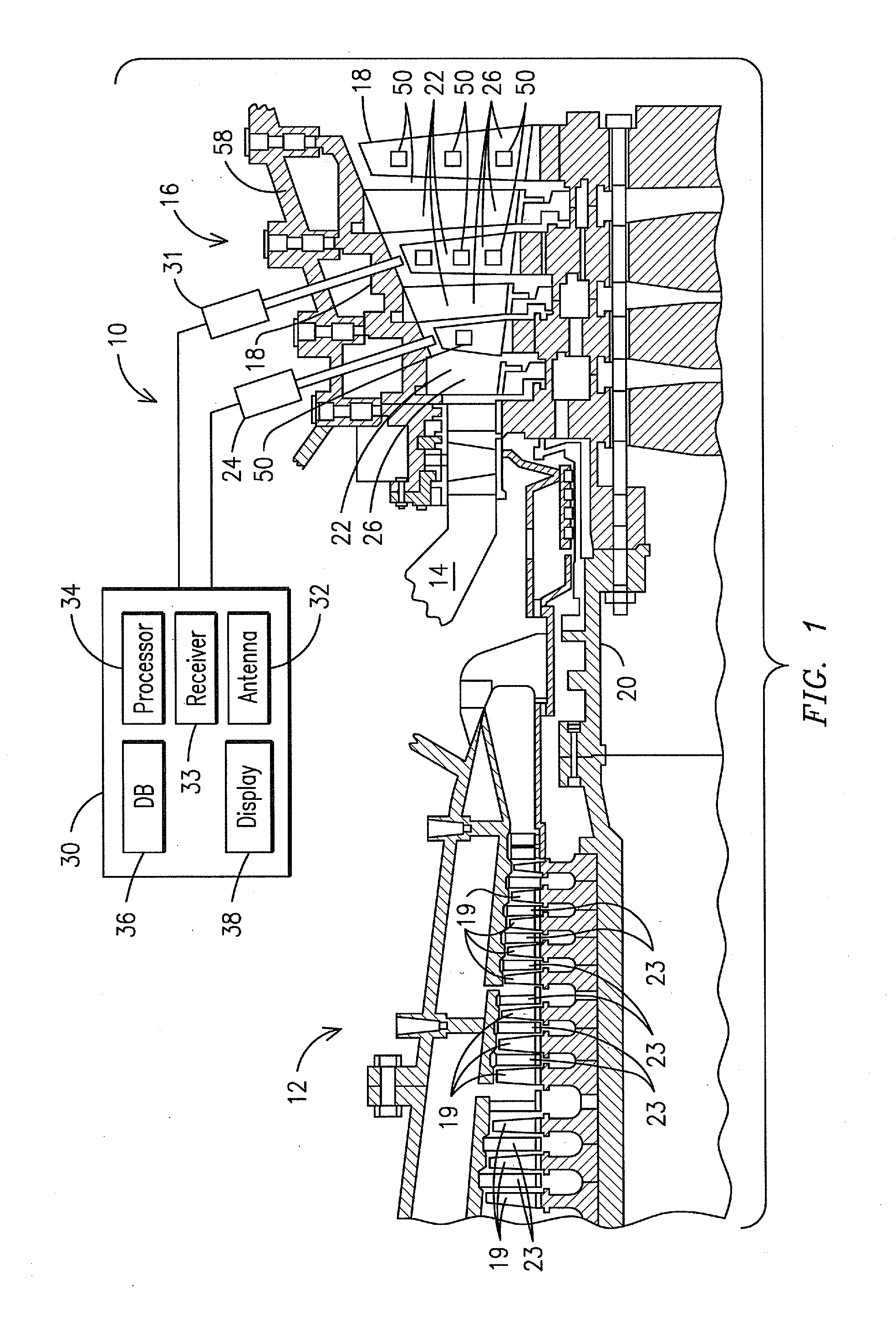
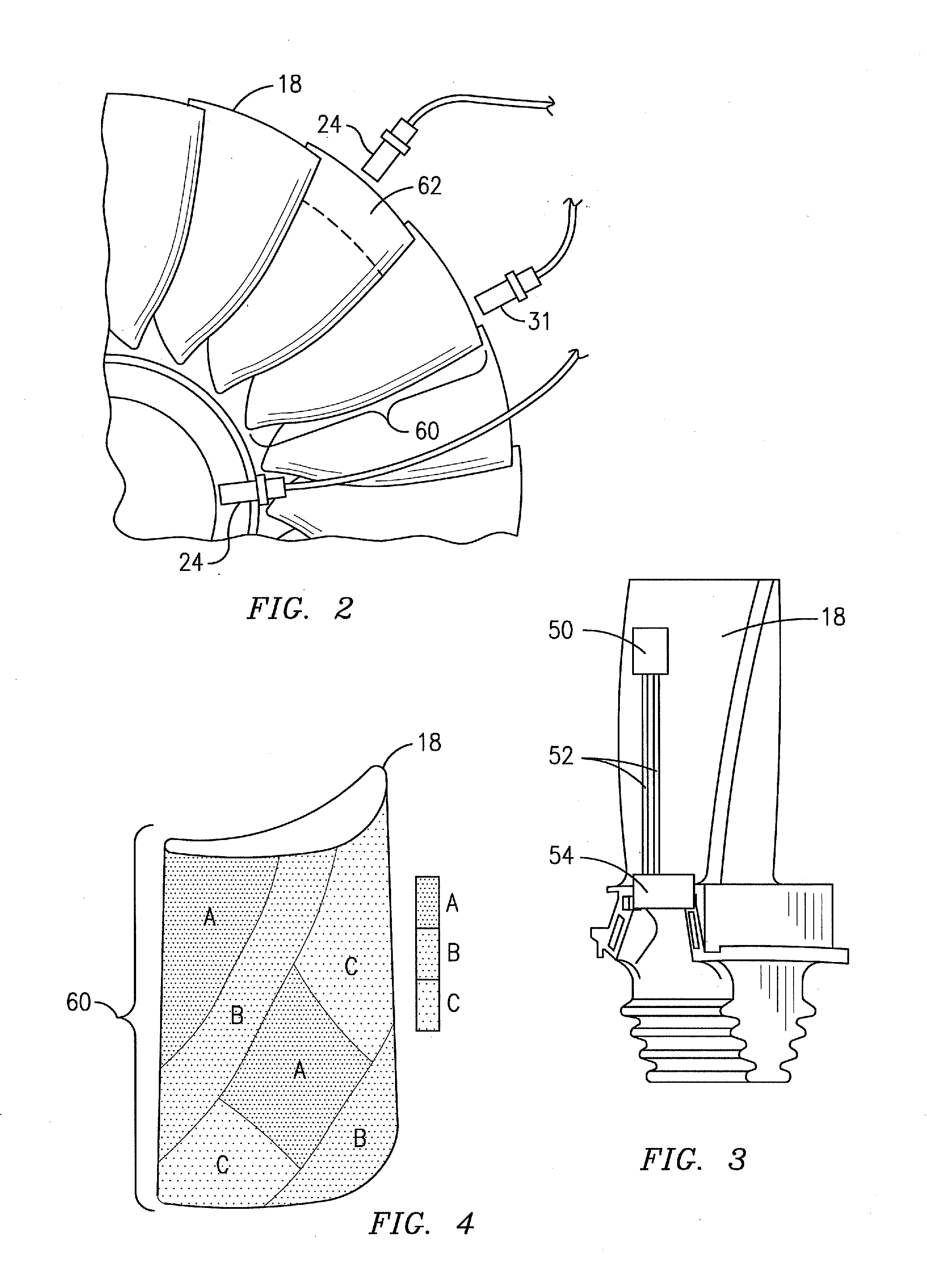
[0014]FIG. 1 illustrates an exemplary combustion turbine 10 such as a gas turbine used for generating electricity incorporating non-contact sensors and point sensors placed at various positions to monitor operating conditions of stationary and moving components of the turbine machine 10 for diagnosing performance of these various components. Embodiments of the invention may be used with a combustion turbine 10 or in numerous other operating environments and for various purposes as will be recognized by those skilled in the art. For example, embodiments may be used in aircraft engines and in the automotive industry for monitoring various operating conditions of stationary and moving components. As will be explained in more detail below, the sensors may be used to monitor temperature configurations, vibrational modes (bending, twisting, elongation, etc.), strain, acceleration, gas content of fluid flowing across or over such components and various other operating conditions. For purpo...


PUM


Abstract

A diagnostic system and method for monitoring operating conditions of turbine machine components (18, 19, 22, 23) that comprise one or more non-contact sensors (24, 31) that detect an operating condition of a turbine component (18, 19, 22, 23) over a defined region of the component. In addition, point sensors (50) are provided that detect and monitor the same operating condition within the defined region. Data generated from the point sensor (50) is used to calibrate the non-contact sensor (24, 31) and the data generated by the non-contact sensor (24, 31).

Description

FIELD OF THE INVENTION[0001]The present invention relates generally to monitoring operating environments of a turbine and, in particular, to monitoring operating conditions of components that are enabled for transmitting data with respect to the condition of individual components. In addition, the present invention relates to the use of non-intrusive measurement systems for monitoring operating conditions of components of a turbine machineBACKGROUND OF THE INVENTION[0002]Gas combustion turbines are used for a variety of applications such as driving an electric generator in a power generating plant or propelling a ship or an aircraft. Firing temperatures in modern gas turbine engines continue to increase in response to the demand for higher efficiency engines. Superalloy materials have been developed to withstand the corrosive high temperature environment that exists within a gas turbine engine. However, even superalloy materials are not able to withstand extended exposure to the hot...

Claims


Application Information

Patent Timeline
IPC IPC(8): G06F15/00
CPCF01D21/003F05D2260/80Y02T50/67F01D21/00F01K13/00F02C9/00Y02T50/60
Inventor MITCHELL, DAVID J.SUBRAMANIAN, RAMESHULERICH, NANCY H.ZOMBO, PAUL J.
Owner SIEMENS ENERGY INC
Learn More