

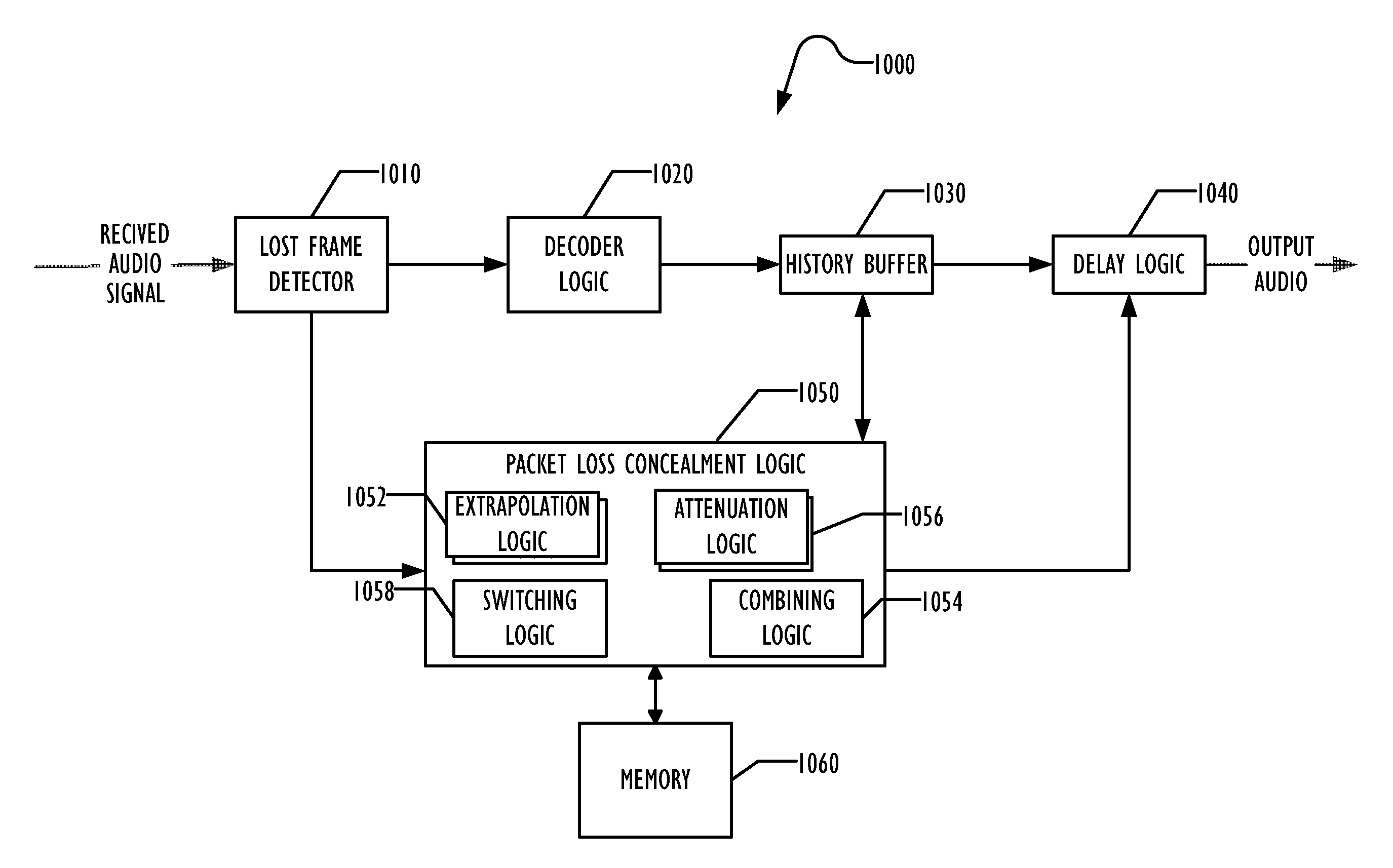
Artifact Reduction in Packet Loss Concealment
a technology of artifact reduction and packet loss concealment, applied in the field of reducing artifacts caused by packet loss concealment, can solve the problems of erasures being inaudible after concealment, affecting the effect of erasure, so as to improve packet loss concealment and reduce artifacts
- Summary
- Abstract
- Description
- Claims
- Application Information
AI Technical Summary
Benefits of technology
Problems solved by technology
Method used
Image

Examples
second embodiment
[0035]In a second embodiment, the fixed period of time before beginning attenuation is replaced with a varying period of time. A balance of smoothness to artifacts can be obtained by choosing this varying period as a function of PitchLength(x[n]). Thus, for example, the time before starting to attenuate the extrapolation may be longer when the audio signal has a longer pitch period and shorter when the pitch period is shorter.
[0036]FIG. 4 is a flowchart illustrating attenuation using a variable attenuation time according to one embodiment as described above. In block 410, audio is extrapolated for insertion into the output audio for PLC purposes. Block 420 calculates how long the extrapolation should run before beginning to attenuate the extrapolation. As described above, this pre-attenuation time may vary as a function of the pitch period of the most recent sample. In block 430, once the pre-attenuation time has expired, the extrapolation is attenuated to silence or to a synthesize...
third embodiment
[0037]In a third embodiment, the rate of attenuation is made variable. In the prior art, the attenuation is done for a fixed amount of time and often follows a linear pattern. In this embodiment, Audio Character Measures 1, 2, 3, and 4 may be used to estimate the risk of artifacts during extrapolation. In most cases, the envelope of the attenuation starts slowly and gets faster. For adaptation, as audio character measures 1, 2, 3, and 4 imply a higher risk of artifacts, the technique may adapt the attenuation so that the envelope starts with a faster attenuation and ends with a slower attenuation.
[0038]Although the attenuation may be performed over a constant time, in some situations, a faster initial attenuation may be desirable to reduce the risk of artifacts. In other situations, where the artifact risk is lower, a slower initial attenuation followed by a faster attenuation may let the users hear the extrapolation longer, producing a smoother result.
[0039]In one embodiment, if th...
fourth embodiment
[0041]In a fourth embodiment, the periodic extrapolation may be attenuated faster than the non-periodic extrapolation, because the periodic extrapolation is the source of much of the artifacts. In one embodiment, the attenuation of the PE and the attenuation of the NPE component of the total extrapolation may occur at the same rate, but the PE extrapolation may begin to attenuate before the NPE extrapolation attenuates, so that over time, the PE extrapolation has attenuated more than the NPE extrapolation. In one embodiment, the combination of the PE and NPE extrapolation is performed using a weighted sum where the weighting between the PE and the NPE extrapolation components varies over time, typically increasing the weighting given to the NPE extrapolation over time.
[0042]FIG. 6 is a flowchart illustrating a technique for extrapolation using both PE and NPE components according to one embodiment. In block 610, the PE component is generated using any desired technique. In block 620...
PUM
 Abstract
Description
Claims
Application Information