
Bouyant actuator

a technology of actuators and floats, applied in mechanical devices, machines/engines, sea energy generation, etc., can solve the problems of tethers to which the floats are connected, prone to damage or collapse, and floats can be subject to extreme forces, etc., to achieve the effect of adding effective mass

Inactive Publication Date: 2012-05-03
CETO IP
View PDF4 Cites 11 Cited by
  • Summary
  • Abstract
  • Description
  • Claims
  • Application Information

AI Technical Summary

Benefits of technology

[0038]The viscous coupling is reduced upon establishment of the openings. The establishment of the openings allows water to flow through the buoyant actuator to thereby impact upon its movement in the body of water. In effect, the establishment of the openings reduces the effective size or profile of the buoyant actuator that is apparent to the moving water in which it is immersed. In particular, there is a reduction in the velocity and amplitude of motion of the buoyant actuator within the body of water. The reduction of velocity also leads to a reduction in the effective mass of the buoyant actuator. This thus allows the buoyant actuator to assume a condition in which it is less response and also less vulnerable to damage in adverse sea conditions.

Problems solved by technology

While such floats are effective in providing buoyancy, they can be heavy.
When exposed to an aggressive sea state, typically adverse weather conditions (such as in storm conditions), floats can be subject to extreme forces.
Known floats can be prone to damage or collapse when exposed to such conditions.
Further, tethers to which the floats are connected can be damaged or ruptured in such conditions.
Furthermore, such floats are generally not well-suited for intercepting the horizontal wave motions that exist in shallow water conditions.

Method used


Image

  • Bouyant actuator
  • Bouyant actuator
  • Bouyant actuator

Examples


Embodiment Construction

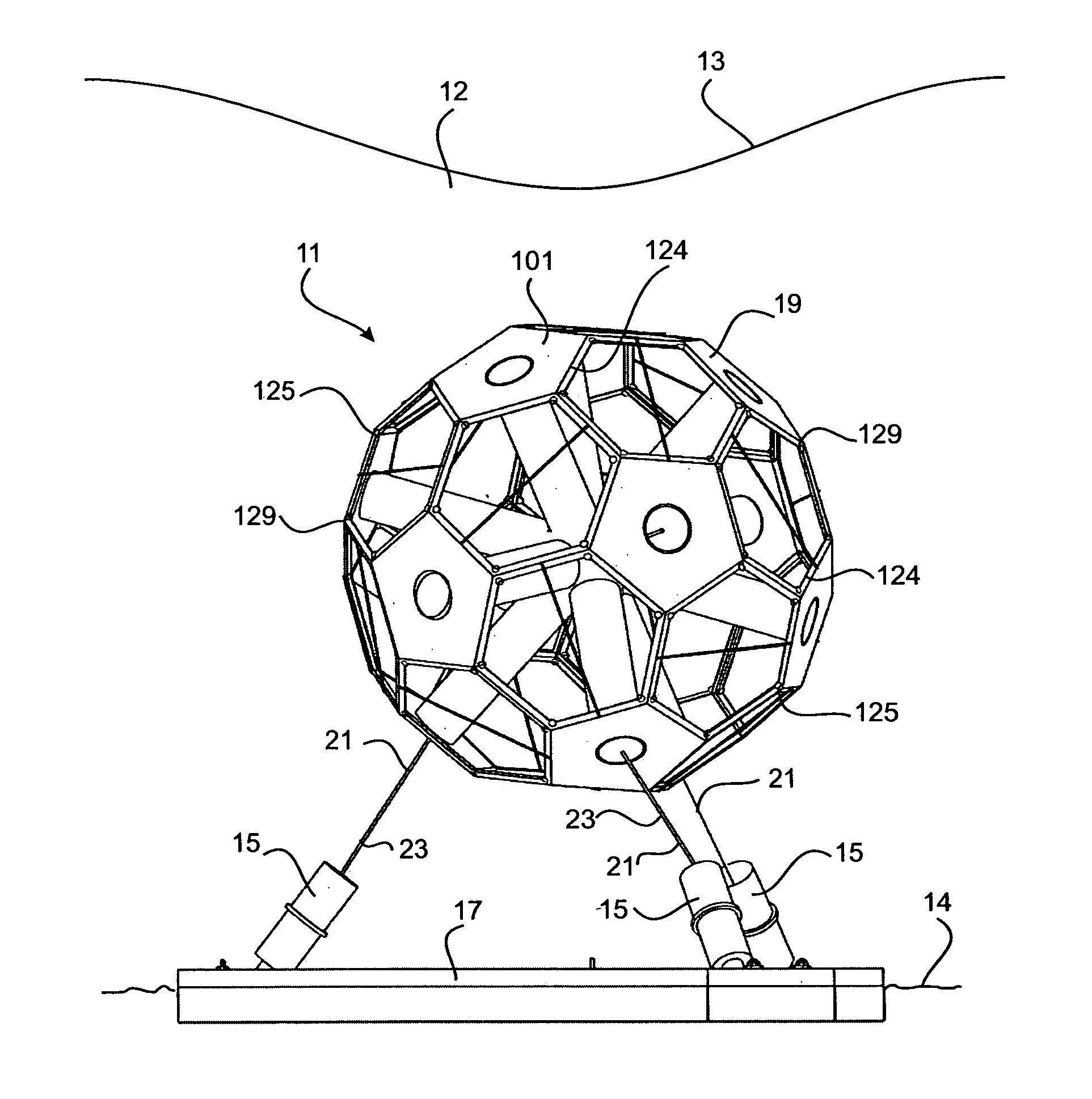
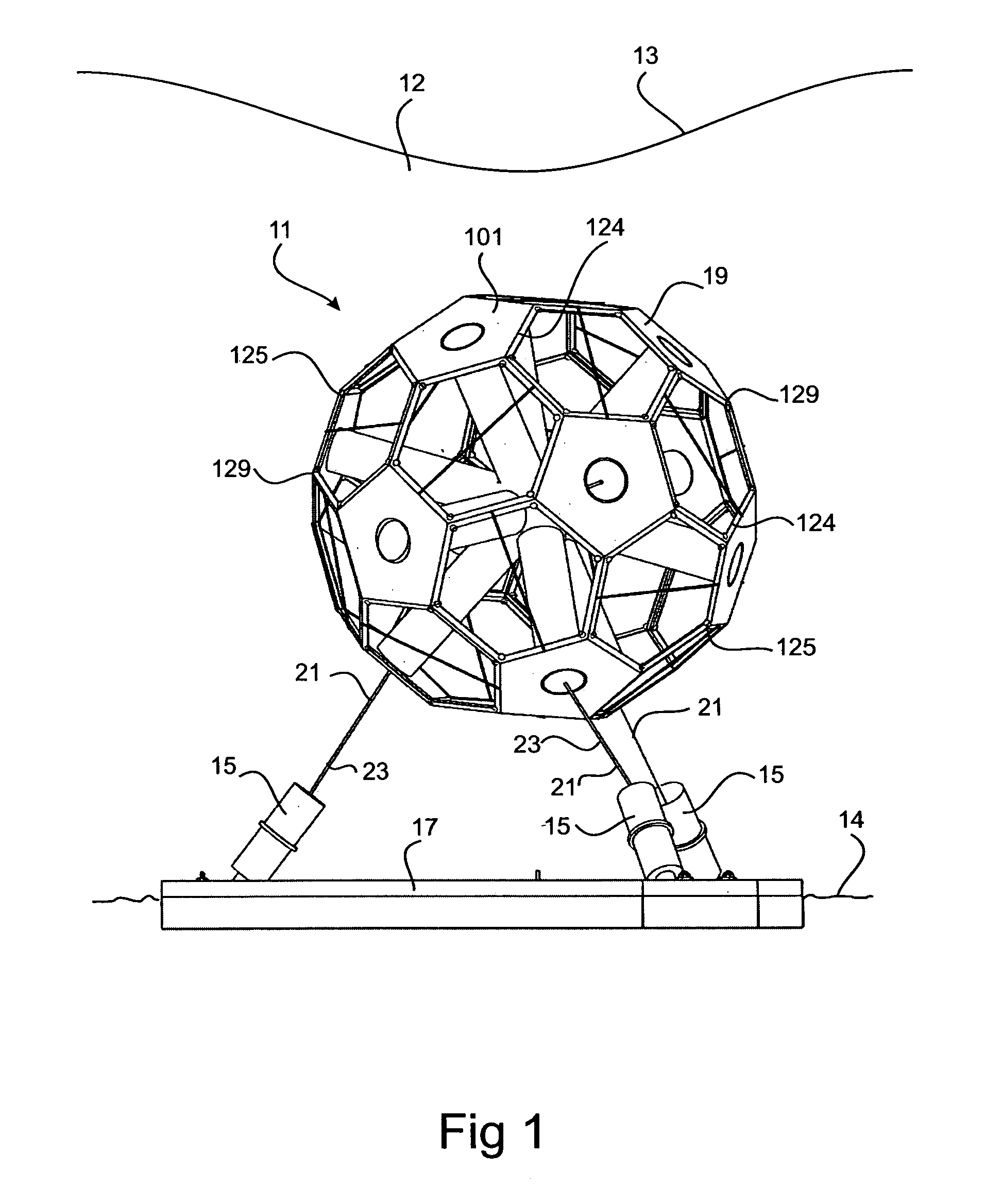
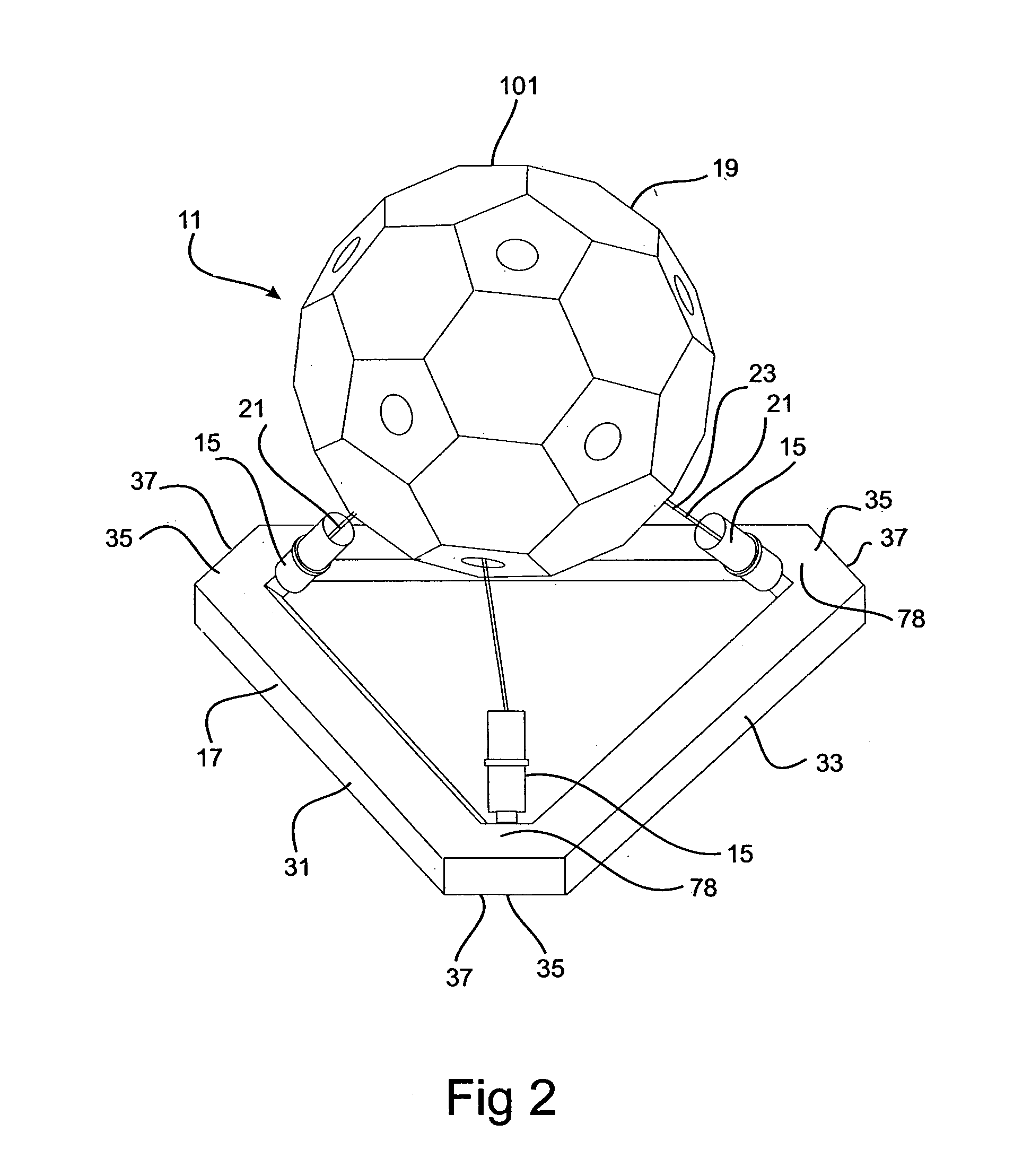
[0070]Referring to the drawings, there is shown a buoyancy actuator 19 used in apparatus 11 for harnessing wave energy in a body of water and for converting the harnessed energy to high pressure fluid, typically above 0.7 MPa and preferably above 5.5 MPa. The high pressure fluid can be used for any appropriate purpose. In the arrangement shown, the high pressure fluid comprises water used for power generation and / or desalination.

[0071]The apparatus 11 is installed for operation in a body of seawater 12 having a water surface 13 and a seabed 14.

[0072]The apparatus 11 comprises a plurality of pumps 15 anchored within the body of water 12 and adapted to be activated by wave energy. The pumps 15 are attached to a base 17 anchored to the seabed 14. Each pump 15 is operably connected to a buoyant actuator 19 according to the embodiment buoyantly suspended within the body of seawater 12 above the pumps but below the water surface 13 at a depth such that it is typically a few metres below t...


PUM


Abstract

A buoyant actuator (19) for coupling wave motion to a device operable in response to wave motion in a body of water. The buoyant actuator (19) comprises a generally spherical body (20) defining an exterior surface and a hollow interior adapted to contain water received from the body of water. The exterior surface comprises a plurality of facets (101) which are tessellated. Typically, there are 36 facets (101), of which 12 comprise generally pentagonal facets (105) and 24 comprise generally hexagonal facets (107). The body (20) comprises a plurality of openings (143) for fluid flow between the hollow interior and the surrounding body of water. A closure configured as a flap (145) is provided for each opening (143) to block or at least inhibit fluid flow therethrough, the closure being adapted to move away from the opening to permit fluid flow therethrough in response to a predetermined fluid pressure differential imposed thereon between the hollow interior and the surrounding body of water. The exterior surface of the body (20) is configured to viscously couple with water surrounding the body (20). The viscous coupling between the surrounding water and the exterior surface of the body (20) provides added effective mass to the buoyant actuator (19) which is additional to the physical mass of the buoyant actuator and the mass of the volume of water contained in the body.

Description

FIELD OF THE INVENTION[0001]This invention relates to a buoyant actuator responsive to wave motion, and more particularly a buoyant actuator for coupling wave motion to a device operable in response to wave motion. The invention also relates to a wave energy conversion system.[0002]The invention has been devised particularly, although not necessarily solely, as a buoyant actuator for harnessing wave energy and for converting the harnessed energy to linear motion for driving an energy conversion device such as a fluid pump or a linear electric generator. In such an arrangement, the buoyant actuator may be operably connected to the energy conversion device, the actuator being buoyantly suspended within the body of water, but typically below the water surface. The buoyant actuator is in effect a submerged float which moves in response to wave action within the body of water.BACKGROUND ART[0003]The following discussion of the background art is intended to facilitate an understanding of ...

Claims


Application Information

Patent Timeline
IPC IPC(8): F03B13/18
CPCF03B13/14Y02E10/38F05B2250/241F05B2220/707F05B2240/97F03B13/187Y02E10/30
Inventor BURNS, ALAN ROBERTTINC, PETRUKEYS, MATT
Owner CETO IP
Learn More