
Internal pressure boost system for gas utility pipelines

a technology for gas utility pipelines and pressure boosters, which is applied in the direction of mechanical equipment, transportation and packaging, and valve types, etc., can solve the problems of inability to increase the pressure rating, the number of miles of gas pipelines is unable to increase, and the pressure rating cannot be increased, so as to increase the overall pressure of the system

Active Publication Date: 2012-05-03
GAS TECH INST
View PDF9 Cites 12 Cited by
  • Summary
  • Abstract
  • Description
  • Claims
  • Application Information

AI Technical Summary

Benefits of technology

[0008]Accordingly, it is one object of this invention to provide a system that can provide a local boost gas supply (at one or multiple locations) into a pipeline when needed without substantially increasing the overall pressure of the system.
[0009]It is another object of this invention to provide a system for boosting the pressure of gas pipelines in “zones” along the length of the gas pipeline where the draw off of gas is greatest.

Problems solved by technology

In the United States today, there are thousands of miles of gas pipelines that are unable to increase pressure to increase capacity to meet the increases in demand for the gas.
Low pressure gas pipelines are particularly susceptible to this problem.
Unfortunately, the current low pressure systems already operate at their maximum pressure rating.
This pressure rating cannot be increased as the entire system is designed to be of the same pressure required to safely operate end-use appliances.
High end-use demand results in local low pressures in the gas main that can cause inadvertent shutdown of appliances.
At present, there are no known systems in existence that completely solve this problem without major changes or wholesale replacement of the distribution pipeline.
The first option generally requires all service lines to be replaced and taps to be installed along with the service lines, which is either prohibitively expensive or logistically impossible.
The second option has issues with bridging sharp bends, mechanical couplings, and non-full bore openings and is an expensive process that requires a very thorough cleaning prior to lining, an expensive process to reattach taps, and regulators at each residence and, possibly, replacement of the service lines to handle the higher pressures.

Method used


Image

  • Internal pressure boost system for gas utility pipelines
  • Internal pressure boost system for gas utility pipelines
  • Internal pressure boost system for gas utility pipelines

Examples


Embodiment Construction

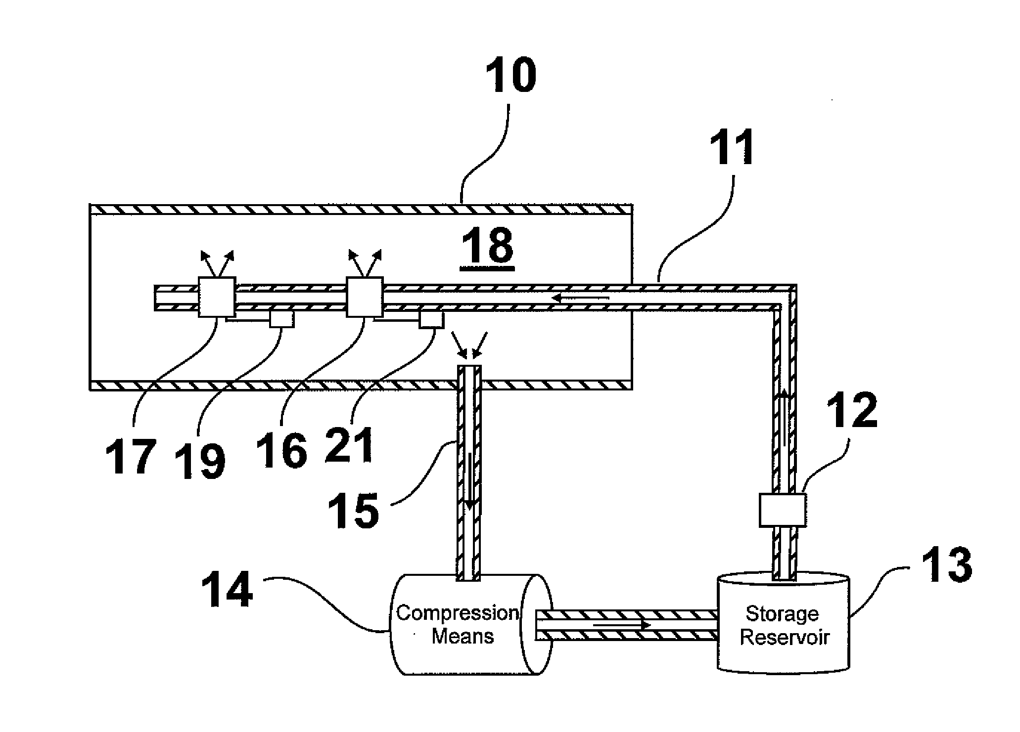
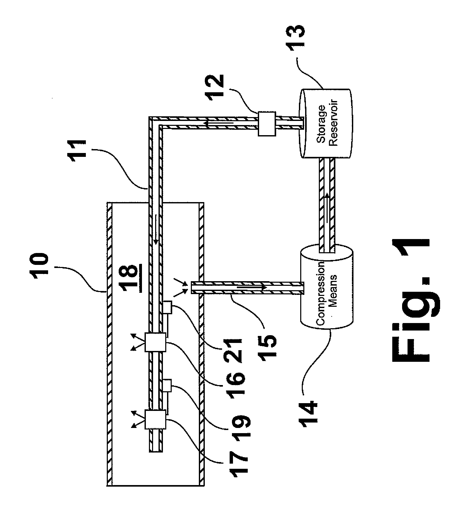
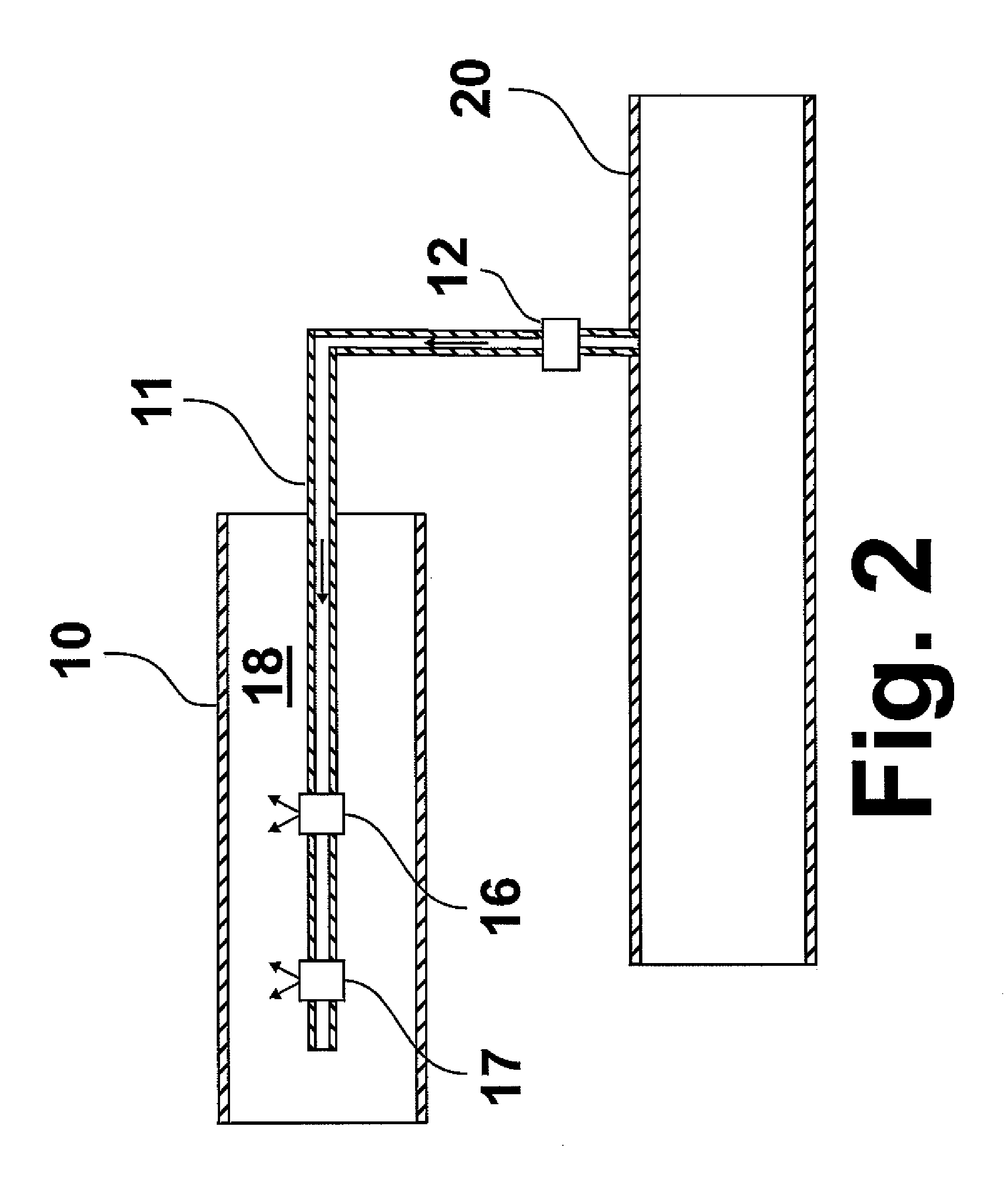
[0014]The fundamental concept of this invention involves the boosting of gas pressure in a pressurized gas main or pipeline on an as-needed basis from within the pressurized gas main or pipeline. The basic components of a system for implementation of this concept comprise a pressurized pipeline gas source providing a supplemental pressurized pipeline gas having a pressure greater than the pressure of the pipeline gas within the pressurized gas pipeline to which the concept is applied, delivery means for delivery of the supplemental pressurized pipeline gas from the pressurized pipeline gas source to the inside of the pressurized gas pipeline, pressure sensing means for sensing the pressure of the pipeline gas in the pressurized gas main or pipeline and the supplemental pressurized pipeline gas and determining the pressure differential between the pipeline gas pressure and the supplemental pressurized pipeline gas pressure, and flow control means for controlling the flow of supplemen...


PUM


Abstract

A method and system for boosting pipeline gas pressure in a low-pressure gas pipeline in which a supplemental gas supply pipe in fluid communication with a supplemental pipeline gas supply is provided to an interior of a gas pipeline containing a pressurized pipeline gas, where the pressure of the supplemental pipeline gas supply is greater than the pressure of the pressurized pipeline gas. The gas pressure differential between the pressurized pipeline gas and the supplemental pipeline gas supply pressure is measured. When the pressure differential reaches a certain predetermined set value, supplemental pipeline gas is provided from the supplemental pipeline gas supply through the supplemental gas supply pipe into a pipeline space between the gas pipeline and the supplemental gas supply pipe. The flow of supplemental pipeline gas is halted upon achievement of a second predetermined set differential pressure.

Description

BACKGROUND OF THE INVENTION[0001]1. Field of the Invention[0002]This invention relates to a method and system for boosting the internal pressure of pressurized pipelines. In one aspect, this invention relates to a method and system for boosting the internal pressure of pressurized pipelines from inside the pressurized pipelines.[0003]2. Background of the Invention[0004]In the United States today, there are thousands of miles of gas pipelines that are unable to increase pressure to increase capacity to meet the increases in demand for the gas. Low pressure gas pipelines are particularly susceptible to this problem. By low pressure gas pipelines, we mean gas pipelines in which the gas pressure is in the range of inches of water column to about 2 psig. Cast iron pipeline systems are in some of the most densely populated locations in the United States. For example, in the northeastern United States, some of the largest local distribution companies (LDCs) have low pressure cast iron dist...

Claims


Application Information

Patent Timeline
IPC IPC(8): F17D3/01F16K17/34F17D1/04
CPCF17D1/04F16K17/34F17D3/01F17D1/07Y10T137/0396Y10T137/2564Y10T137/7754Y10T137/2572Y10T137/87652
Inventor ERSOY, DANIEL ALLENGERMATA, DANIEL THOMAS
Owner GAS TECH INST
Learn More