Method of reducing the object-traveling resistance

Inactive Publication Date: 2012-05-03
LIN ZUEI LING
View PDF26 Cites 6 Cited by
  • Summary
  • Abstract
  • Description
  • Claims
  • Application Information

AI Technical Summary

Benefits of technology

[0009]The primary objective of the present invention is to provide a method of reducing the object-traveling resistance, and the method forms a plurality of small cavities on an object skin by a non-destructive measure, and produces a plurality of small vortexes at the object skin to form a thin turbulent boundary layer when a fluid is passed through the plurality

Problems solved by technology

In addition, projectiles such as bullets and cannon balls travel with a linear movement plu

Method used


Image

  • Method of reducing the object-traveling resistance
  • Method of reducing the object-traveling resistance
  • Method of reducing the object-traveling resistance

Examples


Example

[0024]With reference to FIG. 8 for an object 10 including a land, sea, or air vehicle 10A, the object 10 includes a flight vehicle 11 (an airplane, a helicopter, etc), a ship 12, a train 13 or a rocket 14, etc. The object also includes a hanging tool or article, and a jet engine hanged onto the vehicle 10A and a ship including a hull above Plimsoll line, a ship bridge, and a hull below Plimsoll line, etc.

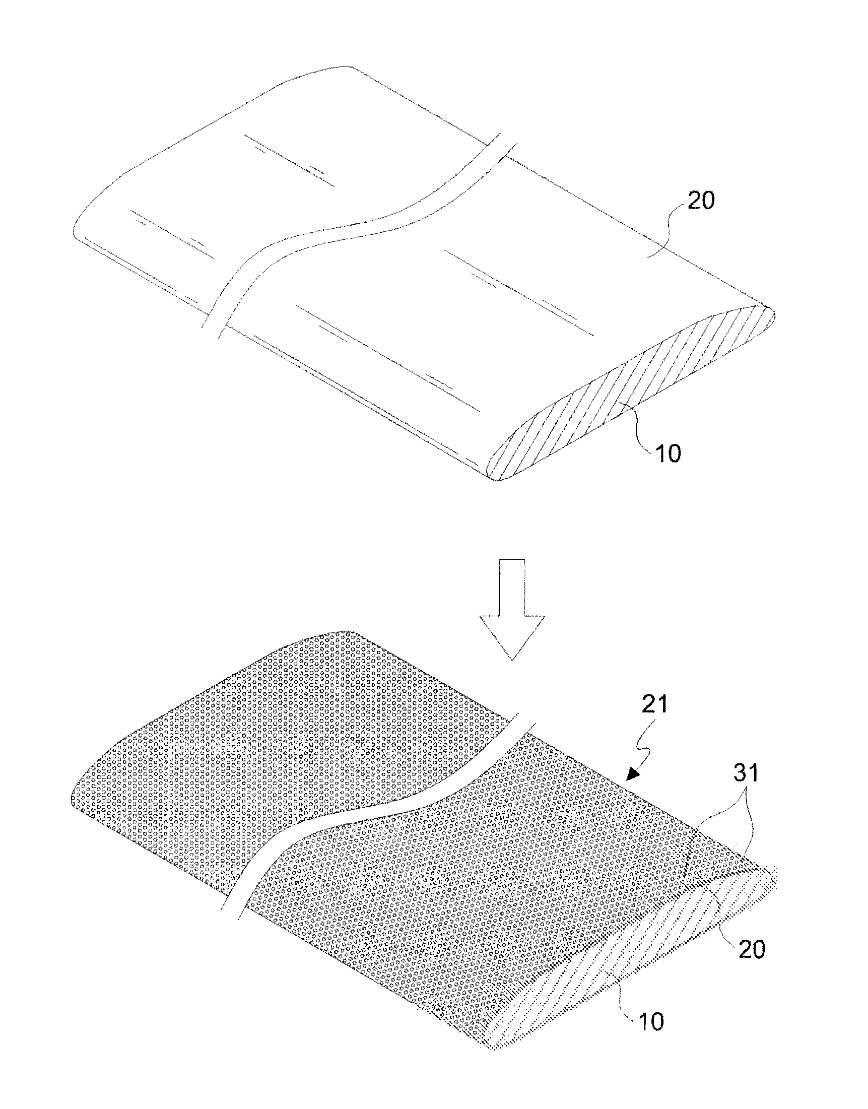
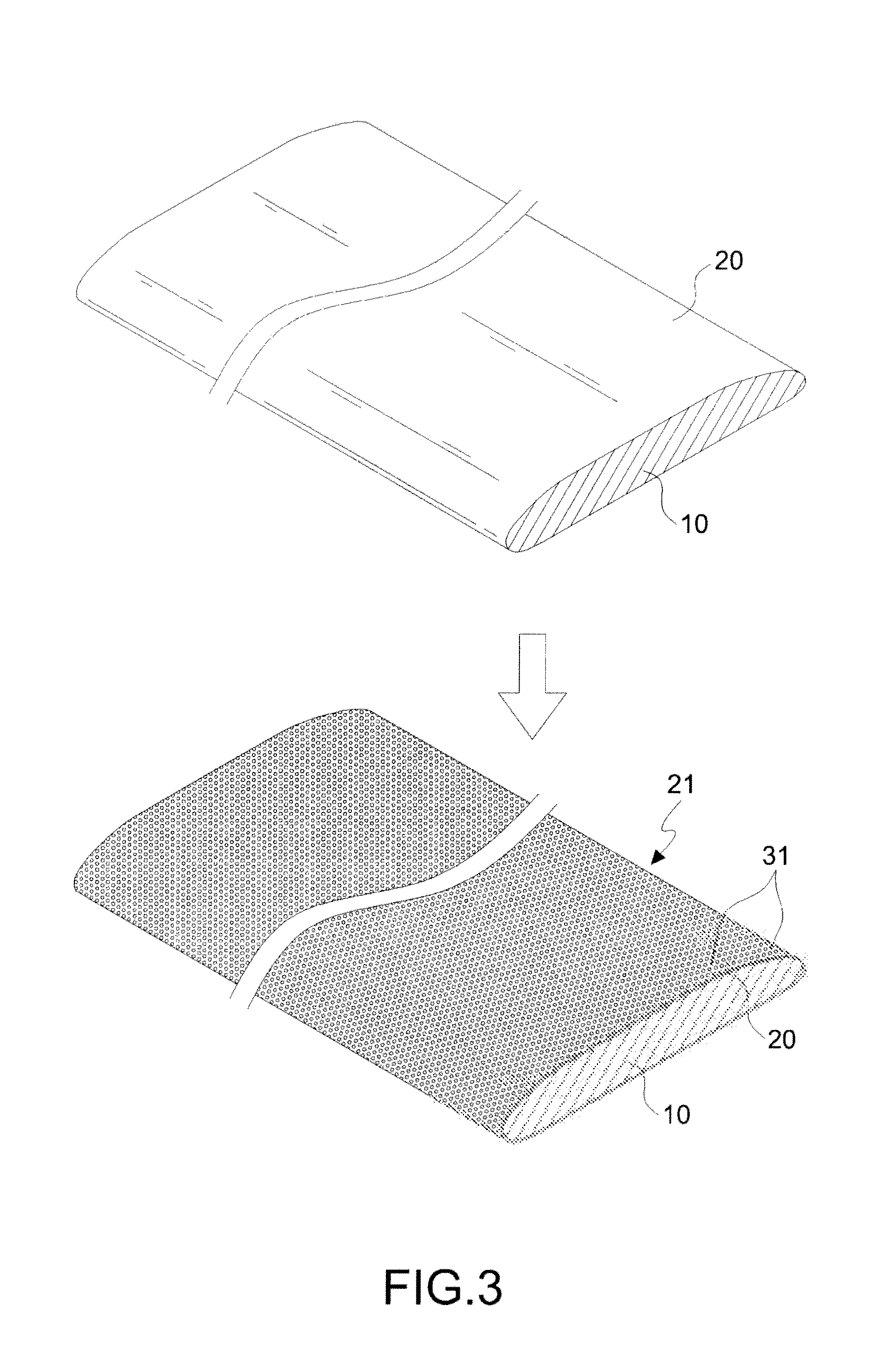
[0025]With reference to FIG. 9 for an object 10 of the present invention, the object 10 includes a land, sea, or air projectile 10B such as a bullet 15, a bomb 16, a missile 17 and a torpedo 18, etc. The foregoing object 10 produces frictional resistance between an object skin of the object 10 and a fluid (air and water), regardless of traveling in a linear movement or a linear movement plus a circular movement. Therefore, the present invention uses an object skin 20 of the vehicle 10A or projectile 10B as a design for reducing the traveling resistance, and the projectile 10B such a...


PUM

PropertyMeasurementUnit
Areaaaaaaaaaaa
Depthaaaaaaaaaa
Depthaaaaaaaaaa

Abstract

A method of reducing the object-traveling resistance includes the steps of forming a plurality of small cavities on the whole or at least a portion of an object skin by a non-destructive measure, and producing a plurality of small vortexes at the object skin to form a thin turbulent boundary layer when a fluid passes through the plurality of small cavities, for achieving an advantageous interference to a turbulence of the fluid at the object skin, such that a portion of fluid is not in contact with the object skin, and a viscous drag acting on the object skin is reduced to extend a wake and reduce a drag force of the wake. The aforementioned mechanism can reduce the object-traveling resistance to provide a faster traveling speed and a big moving power of the object.

Description

BACKGROUND OF THE INVENTION[0001]1. Field of the Invention[0002]The present invention generally relates to objects, and more particularly to a method of reducing the object-traveling resistance.[0003]2. Description of the Related Art[0004]Objects including high speed rails, ships and airplanes travel with a very high speed, and conventional concepts believe that a smoother surface of these vehicles produces less frictional resistance with a fluid. However, the actual practice is not so. In FIGS. 1 and 2, if a fluid 40 is passed through Point A of an object skin 51 of an object 50 smoothly, the viscous drag acting on the object skin 51 obscures the traveling of the fluid 40 to produce a flow field boundary layer instantly, so as to affect and shift a flowing point of the fluid 40 backward, and the resistance produced by shifting the flowing point of the fluid 40 backward is called a reverse pressure which is also known as a resistance of the fluid. When the flowing point of the fluid...

Claims


Application Information

Patent Timeline
IPC IPC(8): B23P6/00
CPCF01D5/145F01D9/02Y02T50/673Y02T50/672F05D2250/60Y10T137/0402Y02T50/60
Inventor LIN, ZUEI-LING
Owner LIN ZUEI LING
Why Eureka
Try Eureka