

Electric vehicle
- Summary
- Abstract
- Description
- Claims
- Application Information
AI Technical Summary
Benefits of technology
Problems solved by technology
Method used
Image

Examples
first embodiment
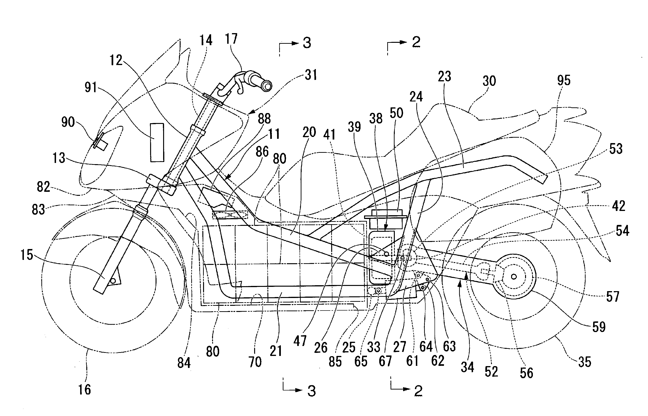
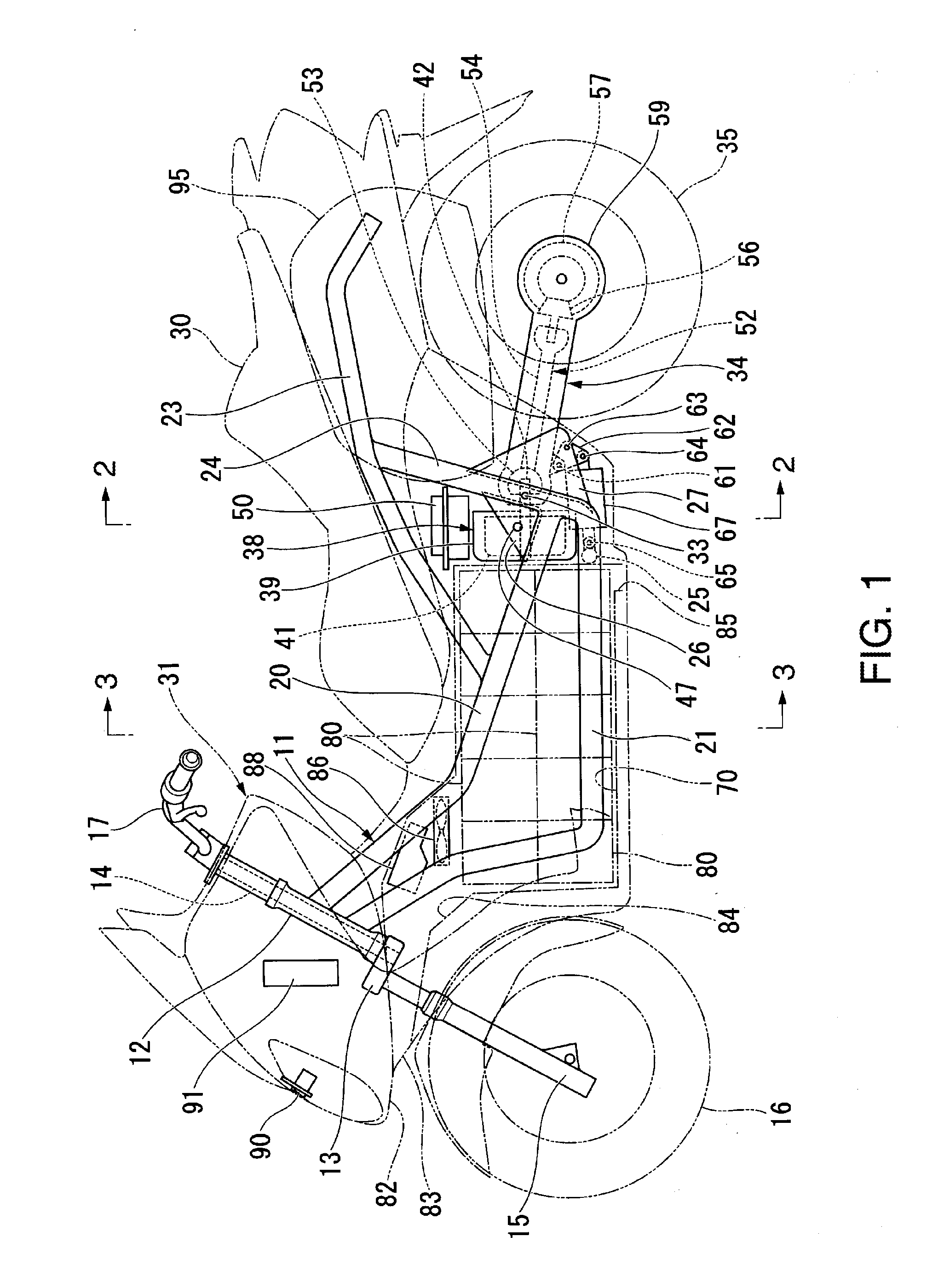
[0028]an electric vehicle is illustrated in FIG. 1 to FIG. 4.
[0029]The first embodiment of the electric vehicle is an electric motorcycle, and includes a vehicle body frame 11 forming the framework of the vehicle body as shown in FIG. 1. A steering shaft 14 provided to a stem 13 is rotatably pivotally supported by a head pipe 12 at the front end of the vehicle body frame 11. In addition, paired left and right front forks 15 are attached to the stem 13. A front wheel 16 is pivotally supported by the lower end portions of the respective front forks 15, and a handlebar 17 is attached to an upper portion on the stem 13. With this configuration, the front wheel 16 is steerable through manipulation of the handlebar 17.
[0030]In addition, the vehicle body frame 11 includes: paired left and right upper frames (main frames) 20 extending rearward, respectively, from the left and right of the upper portion of the aforementioned head pipe 12 on an upper side; and paired left and right lower fram...
second embodiment
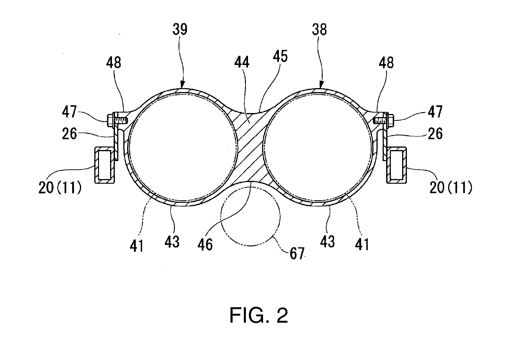
[0065]The electric vehicle of the second embodiment as described above makes it possible to build the electric motors 41 and the swing arm 34 in a single unit, and thereby to improve the assembly workability, because the electric motors 41 swing integrally with the swing arm 34.
[0066]Note that, although the first and second embodiments have been described citing the case where the two electric motors 41 are provided, the invention can be applied to a case where only one electric motor 41 is provided.
[0067]In addition, although the first and second embodiments have been described citing the electric motorcycle, the invention can be applied to things such as an electric four-wheeled vehicle of a saddle riding type in which two rear wheels are supported by a swing arm.
PUM
 Abstract
Description
Claims
Application Information