Fluorescence Light Scanning Microscope Having a Birefringent Chromatic Beam Shaping Device

a chromatic beam shaping and fluorescence light scanning technology, applied in the direction of fluorescence/phosphorescence, luminescent dosimeters, optical radiation measurement, etc., can solve the problem of insufficient wavelength differentiation, short image of intact or even living cells in three dimensions, and vortex phase mask

Active Publication Date: 2012-05-03
DEUTES KREBSFORSCHUNGSZENT STIFTUNG DES OFFENTLICHEN RECHTS
View PDF0 Cites 50 Cited by
  • Summary
  • Abstract
  • Description
  • Claims
  • Application Information

AI Technical Summary

Problems solved by technology

Its popularity has steadily grown despite the fact that it notoriously fails to image structures smaller than about half the wavelength of light (˜200 nm), i. e. that it is limited by the so called diffraction barrier.
While electron, X-ray, and scanning probe microscopy offer a substantially better spatial resolution, they all fall short in imaging intact or even living cells in three dimensions (3D).
However, having

Method used


Image

  • Fluorescence Light Scanning Microscope Having a Birefringent Chromatic Beam Shaping Device
  • Fluorescence Light Scanning Microscope Having a Birefringent Chromatic Beam Shaping Device
  • Fluorescence Light Scanning Microscope Having a Birefringent Chromatic Beam Shaping Device

Examples


Embodiment Construction

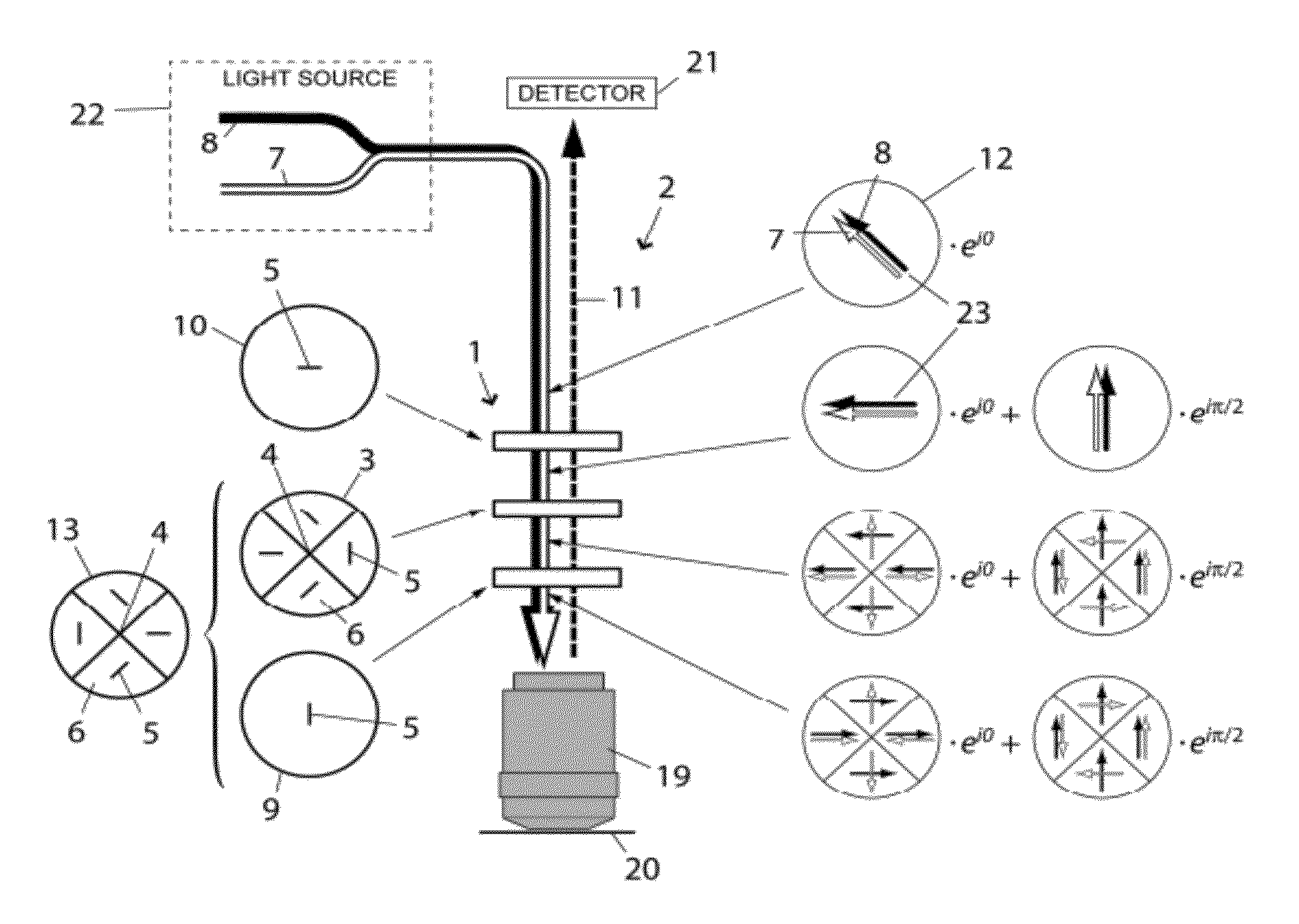
[0029]Even if the invention will be described by particular reference to a STED microscope in which the STED beam is the beam of suppression light in the following, the invention is not limited to STED microscopes but also relates to all other fluorescence light scanning microscopes using a beam of suppression light in addition to a beam of excitation light, like, for example GSD-microscopes or other RESOLFT techniques [10].

[0030]The new fluorescence light scanning microscope comprises a beam shaping device that stands out by the fact that it does not rely on introducing phase differences, but rather on modifying the polarization across the cross section of the beam of suppression light. Working with polarization, one can advantageously use birefringent crystals which are commercially available in high quality as low order optical retarders. Preferably the chromatic characteristics of a low order wave plate exactly match the spectral separation of the excitation and the STED-beam. T...


PUM

PropertyMeasurementUnit
Angleaaaaaaaaaa
Dispersion potentialaaaaaaaaaa
Sizeaaaaaaaaaa

Abstract

A fluorescence light scanning microscope (2) comprises a light source providing excitation light (8) for exciting a fluorophore in a sample to be imaged for spontaneous emission of fluorescence light, and suppression light (7) for suppressing spontaneous emission of fluorescence light by the fluorophore on a common optical axis (4), the suppression wavelength differing from the excitation wavelength; an objective (19) focusing both the excitation (8) and the suppression (7) light to a focus point; a detector (21) detecting fluorescence light (11) spontaneously emitted by the fluorophore; and a chromatic beam shaping device (1) arranged on the common optical axis (4), and including a birefringent chromatic optical element (3) adapted to shape a polarization distribution of the suppression light (7) such as to produce an intensity zero at the focus point, and to leave the excitation light such as to produce a maximum at the focus point.

Description

CROSS REFERENCE TO RELATED APPLICATIONS[0001]This application is a continuation in part of International Patent Application PCT / EP2010 / 056987 filed on May 20, 2010 and claiming priority to German Utility Model DE 20 2009 007 250.9 entitled “Feldveränderungsmittel zur Erzeugung komplementärer Lichtintensitätsmuster, filed on May 20, 2009, and registered on Nov. 26, 2009.FIELD OF THE INVENTION[0002]The invention relates to a fluorescence light scanning microscope. More particular the invention relates to a fluorescence light scanning microscope in which a beam of excitation light for exciting a fluorophore in a sample to be imaged for spontaneous emission of fluorescence light, and a shaped beam of suppression light for suppressing spontaneous emission of fluorescence light by the fluorophore are focused into a focus volume around a focus point, the beam of suppression light being shaped such as to produce an intensity distribution of the suppression light around the focus point havin...

Claims


Application Information

Patent Timeline
IPC IPC(8): G01N21/64
CPCG02B21/0032G02B21/0076G02B21/0068
Inventor REUSS, MATTHIASENGELHARDT, JOHANN
Owner DEUTES KREBSFORSCHUNGSZENT STIFTUNG DES OFFENTLICHEN RECHTS
Why Eureka
Try Eureka