Three-phase electric motor with a low detent torque

a three-phase electric motor and low detent torque technology, applied in the direction of machines/engines, magnetic circuit rotating parts, magnetic circuit shapes/forms/construction, etc., can solve the problems of incompatibility of stators with more economical winding methods, difficulty in controlling residual torque of these motors, etc., to avoid any saturation, economical winding, residual torque

Active Publication Date: 2012-05-03
MMT SA
View PDF10 Cites 12 Cited by
  • Summary
  • Abstract
  • Description
  • Claims
  • Application Information

AI Technical Summary

Benefits of technology

[0003]The requirements in terms of bulk and efficiency of electric motors are leading to the use of high-energy magnets for the production of the rotors and the more the energy of the materials employed is increased, the more difficult it becomes to control the residual torques of the these motors. The cost of these motors depends not only on the costs of the materials employed but also on the costs of the methods used to produce the various elements. It is therefore important to implement simple solutions for the production of the spare parts and for the assembly of the various components of these motors. In particular, the control of the residual torques may lead to forms of stators that are incompatible with the more economical winding methods. Furthermore, the use of these motors at high speeds requires the use of a small number of pairs of poles for the rotor so as to reduce the losses in the motor and in the electronics.
[0004]FIGS. 5 and 6 describe motors of the prior art that make it possible to obtain low residual torques with rotors having a small number of pairs of poles. The motor of FIG. 5 uses a rotor with two pairs of poles and a stator with 6 teeth (91). The stator poles occupy 90% of the available surface area and thus make it possible to obtain a low residual torque. The small notch width results in a long and difficult winding, which is therefore costly and also has a poor bulk factor.
[0008]To this end, the invention relates to a three-phase motor formed by a stator part excited by electric windings and by a rotor with N pairs of poles, the stator part having teeth extending radially from an annular gear. The width of the stator poles is determined on the one hand to avoid any saturation in the tooth, and on the other hand to cancel the effect of the main magnetization harmonics and also so as to allow for an economical winding by allowing for the placement of windings produced outside the stator.
[0009]The stator poles are straight teeth which comprise an arc of circle (17) at their end defining an airgap at the center of the tooth and an airgap which can be enlarged or reduced on each of the sides (18 and 19). This means that the end of the tooth can be of convex or concave shape. The width of the stator pole, which is defined as being the angle at the center which encompasses the whole tooth, and the radius of the arc of circle (17) which forms the end of the tooth, are determined in such a way as to obtain, for each tooth, a residual torque that is as low as possible. The width of the tooth forming the core of the winding is defined according to the maximum energy of the magnets used. This energy can range from 6 to 40 MGOe, but the stator poles represent, in all cases, less than 60% of the available surface area. Thus, ease of winding is guaranteed.
[0010]As FIG. 12 shows, if the geometry of the end of the tooth is adapted according to the energy of the magnets and according to the magnetization harmonics, it still always observes one and the same rule which makes it possible to define an angle alpha (24) which is tangential to the sides (18 and 19) of the stator pole. Since the cancellation of the residual torque is obtained for each of the teeth individually, there is no need to seek a torque compensation between two teeth or a group of teeth as in certain motors of the prior art. New combinations between the number of teeth of the stator and number of pairs of poles of the rotor become useable while retaining all the advantages in terms of residual torque, motor torque constant and ease of industrialization and therefore represent a better trade-off in terms of cost and performance, in particular for high-speed drive applications.BRIEF

Problems solved by technology

The requirements in terms of bulk and efficiency of electric motors are leading to the use of high-energy magnets for the production of the rotors and the more the energy of the materials employed is increased, the more difficult it becomes to control the residual torques of the these motors.
The cost of these motors depends not only on the costs of the materials employed but also on the costs of the methods used to produce the various elements.
In particular, the control of the residual torques may lead to forms of stators that are incompatible with the more economical winding methods.
The small notch width results in a long and difficult winding, which is therefore costly and also has a poor bulk factor.
The 18 stator teeth occupy 70% of the available surface area and thus make it possible to obtain a low residual torque, but require an interleaved winding of the three phases, which is therefore long and costly, and ill-suited to very large mass production.
However, to obtain residual torque values such as those demanded by most industrial or automotive applications, the induction of these rotors must exhibit a very low distortion.

Method used


Image

  • Three-phase electric motor with a low detent torque
  • Three-phase electric motor with a low detent torque
  • Three-phase electric motor with a low detent torque

Examples


Embodiment Construction

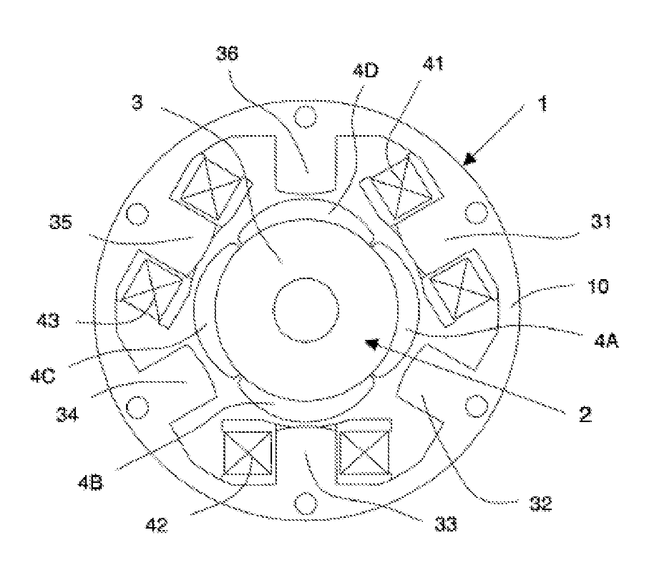
[0031]One of the solutions used to produce a rotor is represented in FIG. 7, this rotor then exhibiting a sinusoidal induction. Four magnet tiles (4A, 4B, 4C and 4D) are glued onto an iron yoke (3). The external shape of these tiles makes it possible to approximate a sinusoidal induction, even if the magnetization of each of the tiles is produced in a single direction. For cost reasons, the geometry of these tiles must, however, remain simple and the manufacturing tolerances cause differences between each of the poles of the rotor. In practice, an induction such as that represented in FIG. 9 is therefore obtained. The harmonic breakdown, shown in FIG. 10, then reveals percentages which are 6.6% for the harmonic 3, 1.2% for the harmonic 5 and 0.6% for the harmonic 7. The aim of the present invention is to propose a simple and economical motor that will make it possible to use rotors with magnetization harmonic percentages of this order of magnitude, while obtaining very low residual ...


PUM


Abstract

The disclosure relates to a three-phase electric motor that uses high magnetic energy permanent magnets and that has a low detent torque. The motor consists of a rotor with N pairs of poles and of a stator portion with teeth extending radially from an annular gear. The teeth have windings and the ends thereof comprise an arc of circle, the middle of which is located on a radius R1 and two sides defining an alpha angle, the vertex of which is located on a radius R2. The ratio R2 / R1 is substantially equal to (1+ / −0.26 / N), and the alpha angle is between 110 and 135°.

Description

CROSS-REFERENCE TO RELATED APPLICATIONS[0001]This application is a National Phase Entry of International Application No. PCT / FR2010 / 000363, filed on May 11, 2010, which claims priority to French Patent Application Serial No. 09 / 02256, filed on May 11, 2009, both of which are incorporated by reference herein.BACKGROUND AND SUMMARY[0002]The present invention relates to a three-phase electric motor using high-efficiency permanent magnets having a low detent torque, in particular for high-speed drive applications in the industrial or automotive field.[0003]The requirements in terms of bulk and efficiency of electric motors are leading to the use of high-energy magnets for the production of the rotors and the more the energy of the materials employed is increased, the more difficult it becomes to control the residual torques of the these motors. The cost of these motors depends not only on the costs of the materials employed but also on the costs of the methods used to produce the variou...

Claims


Application Information

Patent Timeline
Patent Type & Authority Applications(United States)
IPC IPC(8): H02K1/06H02K11/00H02K1/27
CPCH02K1/146H02K29/03H02K1/278H02K1/2781F02M37/08H02K1/145H02K1/165H02K1/2733
Inventor PRUDHAM, DANIELPFISTER, PIERRE-DANIELRICHARD, THIBAUT
Owner MMT SA
Why Eureka
Try Eureka