Flash LED Controller

a technology of led controllers and led lights, applied in the field of flash led controllers, can solve the problems of impracticality of driving them directly with the battery power source, and achieve the effects of high drive current, high efficiency, and high efficiency

Inactive Publication Date: 2012-05-03
TRIUNE IP
View PDF7 Cites 31 Cited by
  • Summary
  • Abstract
  • Description
  • Claims
  • Application Information

AI Technical Summary

Benefits of technology

[0012]The invention has advantages including but not limited to one or more of the following, energy efficiency, area efficiency, and cost-effectiveness in providing high drive currents in systems using relatively low voltage batteries. These and othe...

Problems solved by technology

The voltage requirements of the LEDs are such that driving ...

Method used


Image

  • Flash LED Controller
  • Flash LED Controller
  • Flash LED Controller

Examples


Embodiment Construction

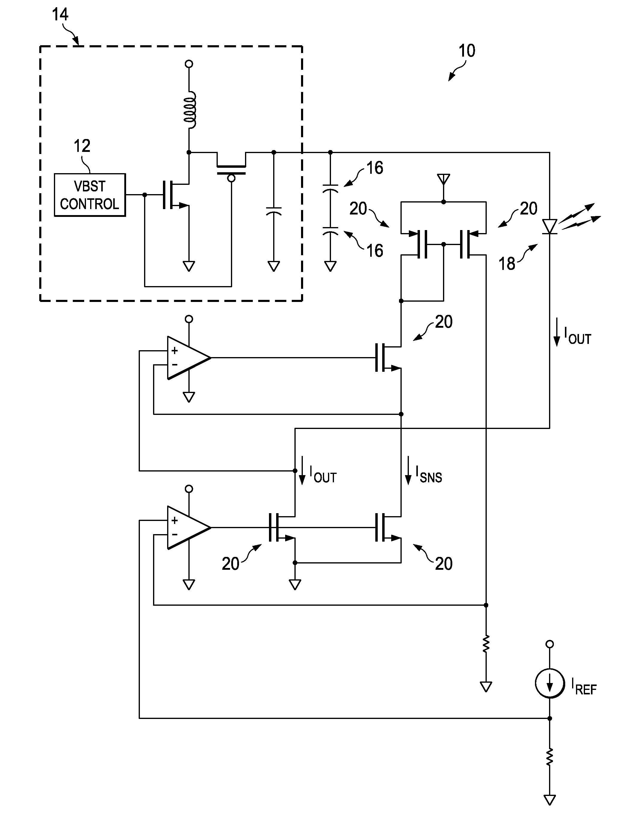
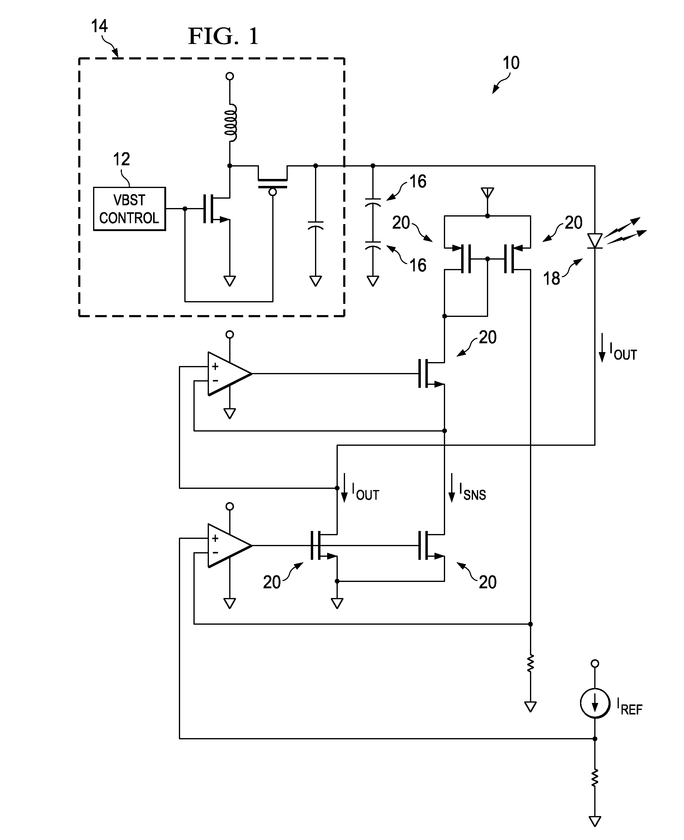
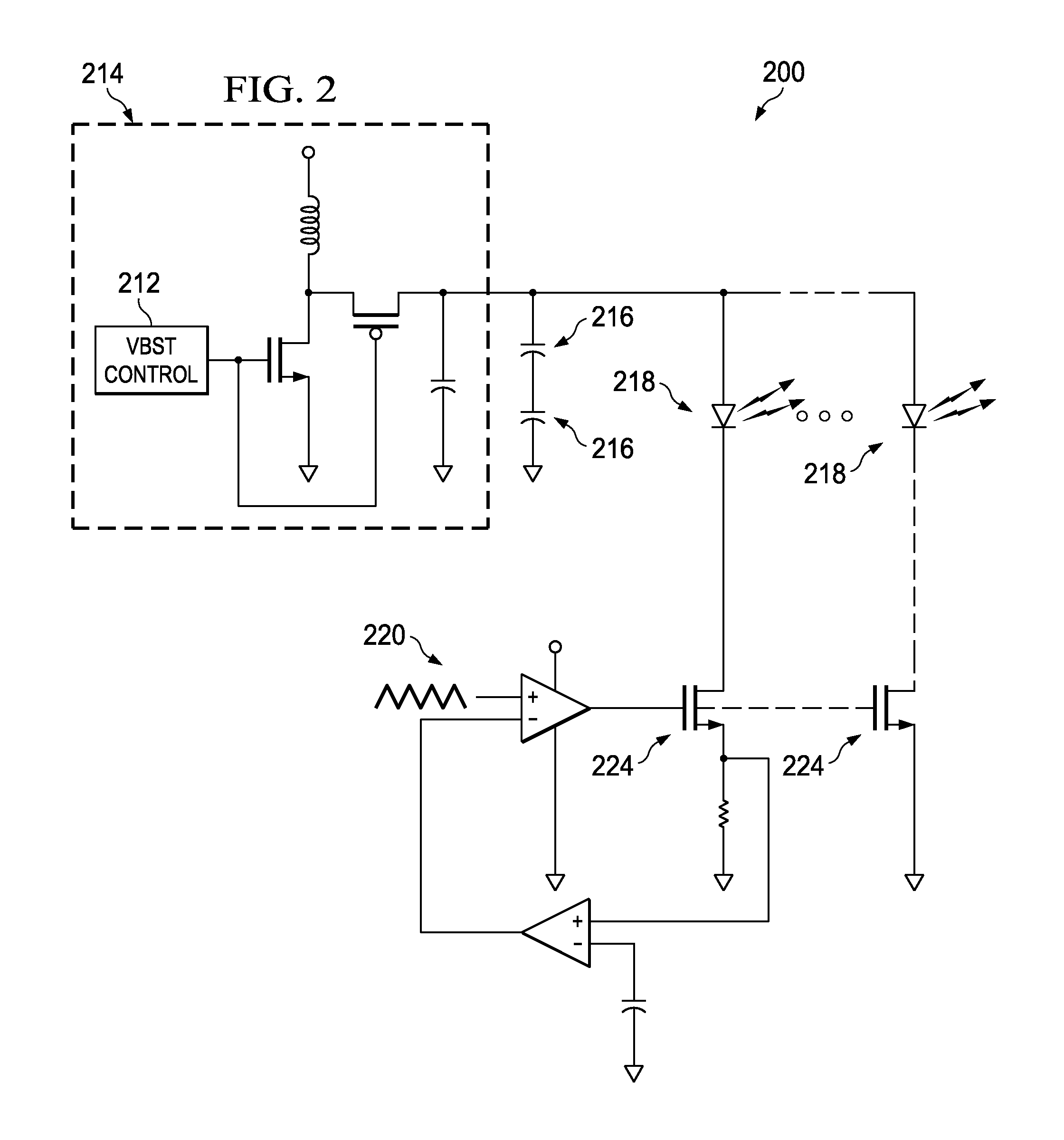
[0020]Addressing the challenges of driving high-current devices in apparatus in which power availability, size and cost are important factors, the inventors have developed an approach using super-capacitors. Generally, the super-capacitors are charged using available battery power and are then used to drive the high-current devices at suitable intervals. Techniques and associated circuitry have been developed for maintaining charge on the super-capacitors and for controlling the supply of current to the driven devices. In an example of a preferred embodiment, a fully-integrated power supply and multi-channel driver for LED applications is configured to charge super-capacitors using a DC / DC synchronous switching boost regulator with fully integrated power switches, internal compensation, and full fault protection. A very low resistance driver is used to energize the driven load, in this example LEDs, with minimal loss of super-capacitor rail voltage headroom. The charging of the supe...


PUM


Abstract

The invention provides integrated power supplies, circuit drivers, and control methods for relatively high-current drivers, usable with common battery power sources. Preferred embodiments include one or more high series resistance super-capacitors electrically connected with a power. A low resistance driver circuit regulates power supplied from the super-capacitors to the load.

Description

PRIORITY ENTITLEMENT[0001]This application is entitled to priority based on Provisional Patent Application Ser. No. 61 / 308,830 filed on Feb. 26, 2010, which is incorporated herein for all purposes by this reference. This application and the Provisional patent application have at least one common inventor.TECHNICAL FIELD[0002]The invention relates to electronics and microelectronic circuitry. In particular, the invention is directed to integrated power supplies, circuit drivers, and control methods.BACKGROUND OF THE INVENTION[0003]It is sometimes desirable to use components with high current requirements in portable electronic apparatus. Problems arise, however with driving high-current devices using common batteries. On the one hand, battery voltage must be sufficient to drive the high-current devices. On the other hand, the current requirements may be so high that there is a risk of damaging the batteries. An example is the use of powerful LEDs as flash elements in small cameras. O...

Claims


Application Information

Patent Timeline
IPC IPC(8): H05B37/02G05F1/10
CPCH05B33/0815H05B33/0827H05B45/38H05B45/46
Inventor CHEN, WAYNEKNIGHT, JONATHANTEGGATZ, ROSSSMITH, BRETTRAJAGOPAL, NARASIMHAN TRICHY
Owner TRIUNE IP
Why Eureka
Try Eureka