Calibration of passive harmonic-rejection mixer

a technology of harmonic rejection and mixer, which is applied in the direction of instruments, electric/magnetic computing, computation using denominational number representation, etc., can solve the problems of difficult realization, hampered rejection of the third and fifth harmonics of the oscillator signal, and more difficult implementation of the passive hr mixer, so as to improve the overall harmonic rejection of the mixer and improve the harmonic rejection

Active Publication Date: 2012-05-03
NXP BV
View PDF2 Cites 9 Cited by
  • Summary
  • Abstract
  • Description
  • Claims
  • Application Information

AI Technical Summary

Benefits of technology

[0010]The inventors propose to improve the Harmonic Rejection, by adopting a segmented approach to the design such as that described in non-prepublished patent application PCT / IB2008 / 054466, and by adding calibration circuitry for calibrating the mixer. More specifically, the inventors propose an electronic device as defined in claim 1 and a calibration method as defined in claim 12. The incremental steps of the mixing waveform are realized using individual sub-mixing stages, and the harmonic conversion products of the mixers substantially cancel one another out when the outputs of the segments are combined together. Therefore, the finite IF amplifier input impedance does not significantly degrade the rejection of the harmonics, and the requirements on the input impedance of the IF amplifiers can be relaxed. The calibration circuitry implements a calibration method for fine-tuning the weighting of each sub-mixer stage, so that the harmonic conversion products of the mixers more fully cancel one another out, improving the overall harmonic rejection of the mixer. Such calibration can help compensate for processing variations and component mis-matches.

Problems solved by technology

On the other hand, a passive HR mixer is more difficult to implement.
Although circuit 100 works well, the rejection of the third and fifth harmonic of the oscillator signal turns out to be hampered by the finite, frequency-dependent input impedance of amplifiers 106 and 108.
This can be difficult to realize, particularly as it needs to be maintained over the frequency range of the received RF signal and its harmonics.
This dependence on the frequency makes it very difficult to compensate for the input impedance, for example in the values of the resistors used in circuit 100.
One reason for this, is that the input impedance of the IF amplifier cannot be made sufficiently small to provide the required accuracy in the weighting of RF currents that is needed to achieve high values of harmonic-rejection.

Method used


Image

  • Calibration of passive harmonic-rejection mixer
  • Calibration of passive harmonic-rejection mixer
  • Calibration of passive harmonic-rejection mixer

Examples


first embodiment

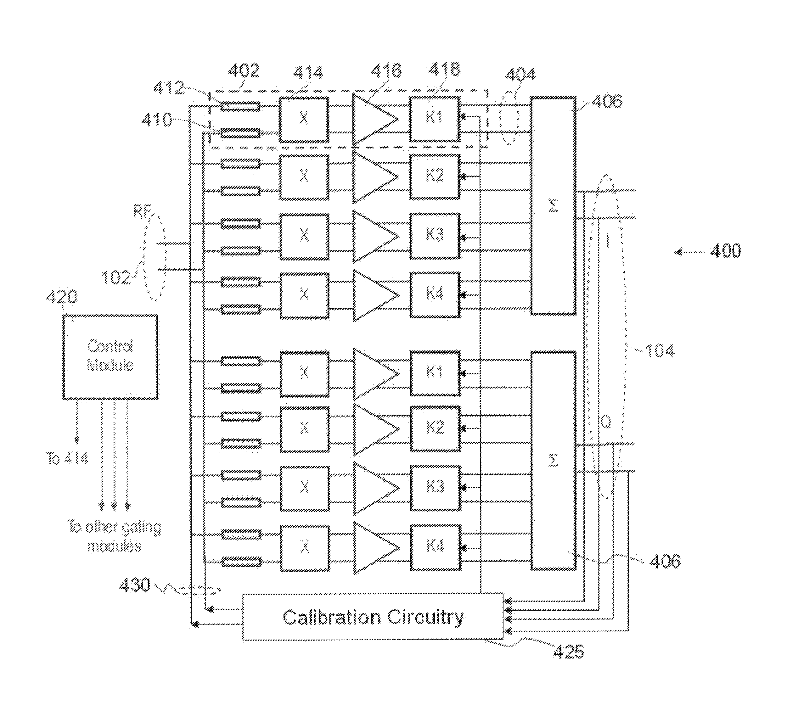
[0021]FIG. 4 is a diagram of an electronic device comprising a passive HR mixer 400 and a calibration circuitry 425 according to the invention. Mixer 400 has an input 102 receiving an RF input signal and an output 104 for supplying in-phase (I) and quadrature (Q) IF output signals. In the example shown, the input signal and output signal are differential signals. The “I” and “Q” signals together form a complex signal from which positive and negative spectral components can be separately extracted. In another example (not shown), only one of the signals “I” and “Q” are generated. The mixer 400 comprises multiple segments that are all of similar configuration connected to the input 102. In order to not obscure the drawing, only one of the segments has been labeled by reference numeral 402.

[0022]The configuration of the segments is now discussed with reference to segment 402, and is applicable to all segments. Segment 402 has a segment output 404 for supplying a weighted contribution t...

fourth embodiment

[0023]The gating module 414 selectively routes or blocks the currents, that are representative of the RF input signal and that flow through segment input resistors 410 and 412, to the inputs of amplifier 416 under control of control signals supplied to gating module 414 by a control module 420. The signal currents are passed either directly (+1) or inverted (−1), or blocked (“0”). The operation of gating module 414 could also be described as that of a tristate module, or of a multiplier that multiplies the currents by a factor +1, a factor 0, or a factor −1. The selective routing and the control signals for the gating module are discussed further below in relation to FIGS. 5, 6, and 7. In other embodiments, for example the fourth embodiment, the gating module multiplies the currents by either +1 or −1, and does not use a blocking state.

[0024]The segment input resistors 410 and 412 act to convert the RF voltage signal into a current signal for the gating module 416, although other me...

second embodiment

[0033]A second embodiment will now be described with reference to FIGS. 9 and 10, which show diagrams of a further mixer 900. This embodiment improves on the conversion efficiency of the mixer 400, the mixer conversion efficiency being defined as the ratio between the power of the IF output signal and the power of the RF input signal. The mixer 900 uses segments in a similar arrangement to the mixer 400 of FIG. 4, however, the segments of the mixer 900 can each comprise multiple sub-mixing stages that are hereinafter referred to as “unit cells”. The unit cells are all substantially identical to one another, and each comprise one gating module and one respective IF amplifier.

[0034]Different segments have different numbers of unit cells. For example, the segment 902 in mixer 900 has 5 unit cells (indicated by the label “5x”), the segment next to it has 4 unit cells (indicated by the label “4x”), etc. As most of the weighting is now implemented in the RF domain by having different numb...


PUM


Abstract

An electronic device comprising a passive harmonic-rejection mixer (400) and a calibration circuitry (425). The passive harmonic rejection mixer has an input (102) connected to several sub-mixer stages (402), and the sub-mixer stages are connected to a summing module (406,408) for generating the output (104). Each sub-mixing stage comprises a gating module (414), an amplifier (416), and a weighting module (418), the gating module selectively passing the input signal or the input signal with inverted polarity under the control of control signals. The calibration circuitry (425) is adapted to input a reference signal (430) to the input of the mixer, receive an output signal (104) from the output of the mixer, and set the weights (K1, K2, K3, K4) of the weighting modules to make the output signal match an expected output signal.

Description

FIELD OF THE INVENTION[0001]This invention relates to calibration of an electronic device comprising a passive harmonic-rejection mixer.BACKGROUND OF THE INVENTION[0002]Switching mixers with rejection properties on one or more odd higher harmonics are well known, see, e.g., J. A. Weldon et al., “A 1.75-GHz highly integrated narrow-band CMOS transmitter with harmonic-rejection mixers”, IEEE Journal of Solid-State Circuits, Vol.36, No.12, December 2001, pp 2003-2015. A harmonic-rejection (HR) mixer allows simplifying the RF filtering. A typical HR mixer known in this field is an active (Gilbert) type of mixer. However, passive mixers are known to provide a better 1 / f noise and higher linearity. On the other hand, a passive HR mixer is more difficult to implement.[0003]FIG. 1 shows a block diagram of an HR mixer 100, as published in WO 2009 / 019633. Mixer 100 is a quadrature mixer. Mixer 100 comprises an RF (radio / frequency) input 102 and an IF (intermediate frequency) output 104. Outpu...

Claims


Application Information

Patent Timeline
Patent Type & Authority Applications(United States)
IPC IPC(8): G06G7/12
CPCH03D7/1441H03D7/1458H03D7/1466H03D7/1483H03D7/1491H03D2200/0086
Inventor JEURISSEN, DENNISDE JONG, GERBEN WILLEMVAN SINDEREN, JANBREKELMANS, JOHANNES HUBERTUS ANTONIUS
Owner NXP BV
Why Eureka
Try Eureka