Capacitive-coupled bandpass filter

Active Publication Date: 2020-07-16
SKYWORKS SOLUTIONS INC
View PDF0 Cites 0 Cited by
  • Summary
  • Abstract
  • Description
  • Claims
  • Application Information

AI Technical Summary

Benefits of technology

[0004]Aspects and embodiments are directed to a capacitive-coupled filter design that provides improved harmoni

Problems solved by technology

However, the conventional capacitive-coupled bandpass filter 100 does not provide adequate harmonic suppres

Method used


Image

  • Capacitive-coupled bandpass filter
  • Capacitive-coupled bandpass filter
  • Capacitive-coupled bandpass filter

Examples


Embodiment Construction

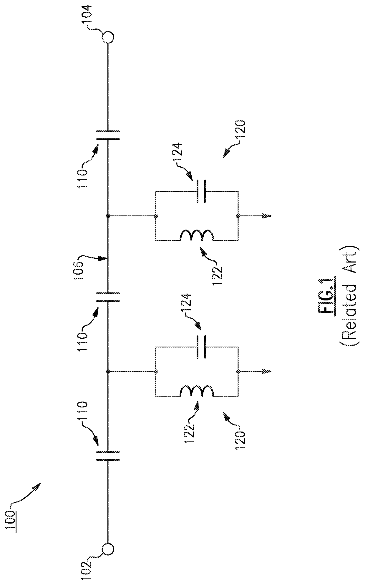
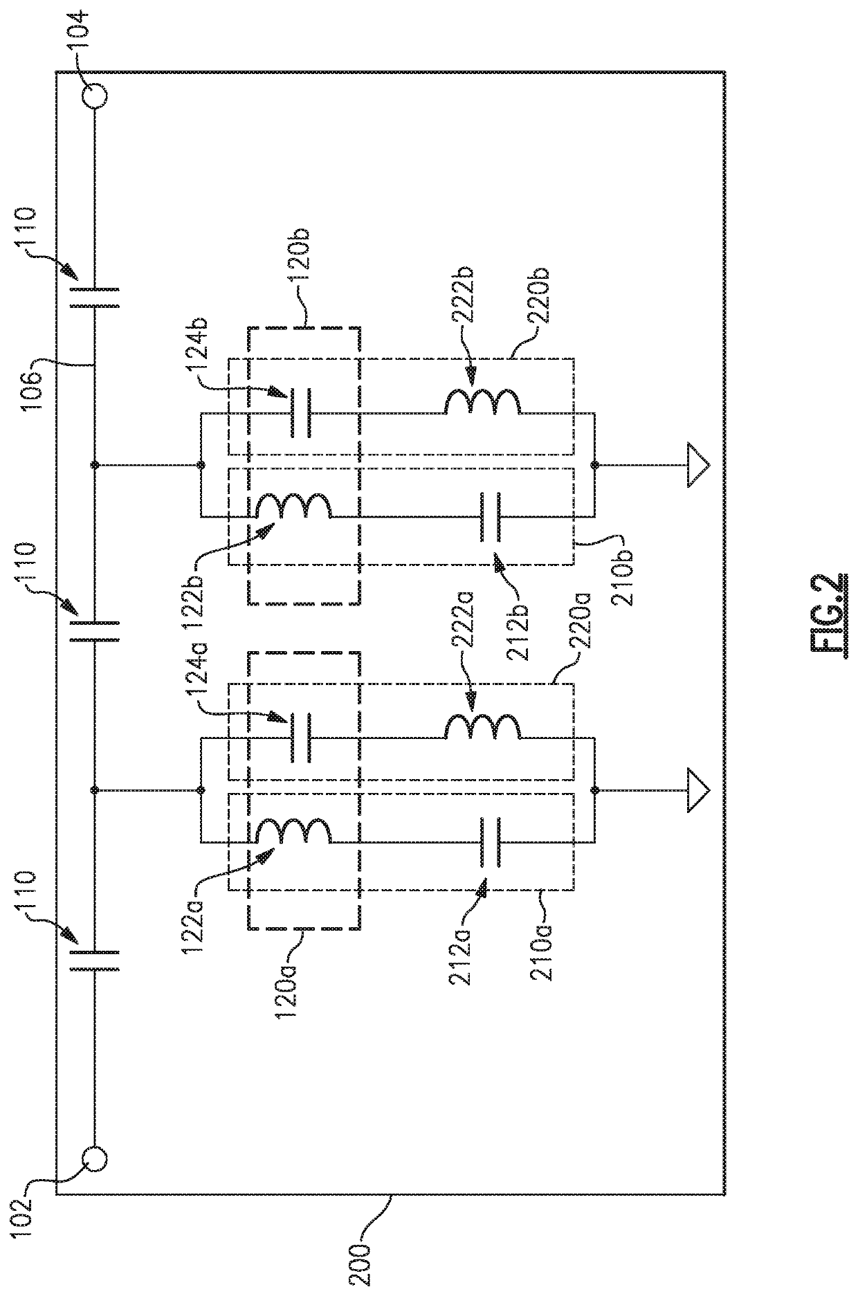
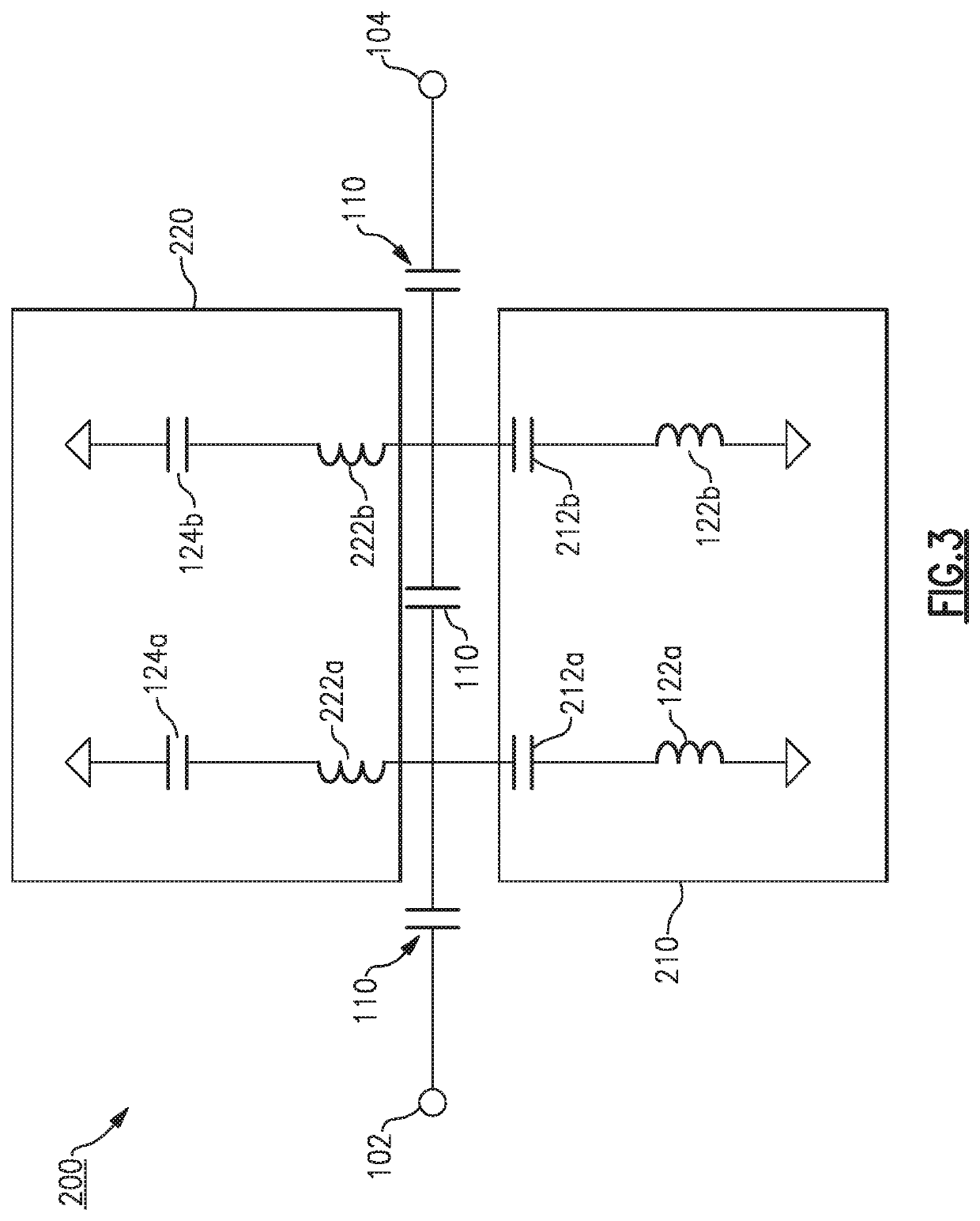
[0029]Aspects and embodiments are directed to capacitive-coupled bandpass filters, and to modules and devices incorporating the same.

[0030]Bandpass filters are used in a variety of wireless device modules and components, including power amplifier and receiver modules. As discussed above, as the operating frequency bands for the filters increases, the ability to achieve low loss, sharp cut-off characteristics, and good harmonic suppression can be limited by the metal loss (skin depth) and Q-factors of the inductors and capacitors used in the filter design. However, ultra-high band bandpass filters may be essential components of modern wireless communications devices as these devices increasingly operate in higher frequency bands. Furthermore, multi-chip module designs used in wireless communications devices can require the filters to have compact size in order to accommodate the many components needed in these devices and to maintain small overall size suitable for handheld devices. ...


PUM


Abstract

Examples of a capacitive-coupled bandpass filter include a plurality of coupling capacitors connected in series along a signal path extending between an input contact and an output contact, a first harmonic suppression notch circuit configured to provide a first harmonic suppression notch in a frequency response of the capacitive-coupled bandpass filter, and a second harmonic suppression notch circuit configured to provide a second harmonic suppression notch in the frequency response of the capacitive-coupled bandpass filter. The first harmonic suppression notch circuit includes a first pair of series L/C resonators connected in shunt between the signal path and a reference potential, and the second harmonic suppression notch circuit includes a second pair of series L/C resonators connected in shunt between the signal path and the reference potential.

Description

CROSS-REFERENCE TO RELATED APPLICATIONS[0001]This application claims priority under 35 U.S.C. § 119(e) to U.S. Provisional Patent application Ser. No. 62 / 792,435, titled “CAPACITIVE-COUPLED BANDPASS FILTER,” filed Jan. 15, 2019, which is incorporated by reference herein in its entirety for all purposes.BACKGROUND[0002]Filters are used in many different modules of communications devices, including wireless devices such as mobile phones. For example, bandpass filters are used in transceivers and radio frequency (RF) front-end modules. As the frequency increases, the ability to achieve a filter design with low loss, sharp cut-off (also called “skirt”) characteristics, and good harmonic suppression is limited by metal loss (skin depth) and the Q-factor of the inductors and capacitors used to make the filters.[0003]A commonly-used bandpass filter design is the capacitive-coupled filter, an example of which is shown in FIG. 1. The capacitive-coupled bandpass filter 100 includes a pluralit...

Claims


Application Information

Patent Timeline
IPC IPC(8): H03H7/01H03H7/12H03H7/46
CPCH03H7/1775H03H7/463H03H7/12H03H7/1758H03H7/0115
Inventor JUNG, DONGJINLEE, HANSEUNGSUN, WEIMIN
Owner SKYWORKS SOLUTIONS INC
Why Eureka
Try Eureka