Beam shaper

a beam shaper and beam technology, applied in the field of beam shapers, can solve the problem that it is difficult to generate more complex radiation profiles, and achieve the effect of reducing the number of beam shapes

Active Publication Date: 2012-05-03
FRAUNHOFER GESELLSCHAFT ZUR FOERDERUNG DER ANGEWANDTEN FORSCHUNG EV
View PDF5 Cites 18 Cited by
  • Summary
  • Abstract
  • Description
  • Claims
  • Application Information

AI Technical Summary

Benefits of technology

[0008]According to an embodiment, a beam shaper for a light source arrangement for generating a radiation profile may have: a multitude of adjacently arranged optical beam-shaping elements, wherein the beam-shaping elements each belong to one type of a plurality of di...

Problems solved by technology

However, respective collimation microlens arrangements...

Method used


Image

  • Beam shaper
  • Beam shaper
  • Beam shaper

Examples


Embodiment Construction

[0041]With reference to FIGS. 1 to 19, embodiments of the present invention will be described below in the form of a beam shaper for a light source arrangement for generating a radiation profile. Before the basic mode of operation as well as implementations of beam shapers according to embodiments of the present invention will be discussed in more detail in the following description, different basic implementations of beam shapers will first be described in the context of FIGS. 1 to 3.

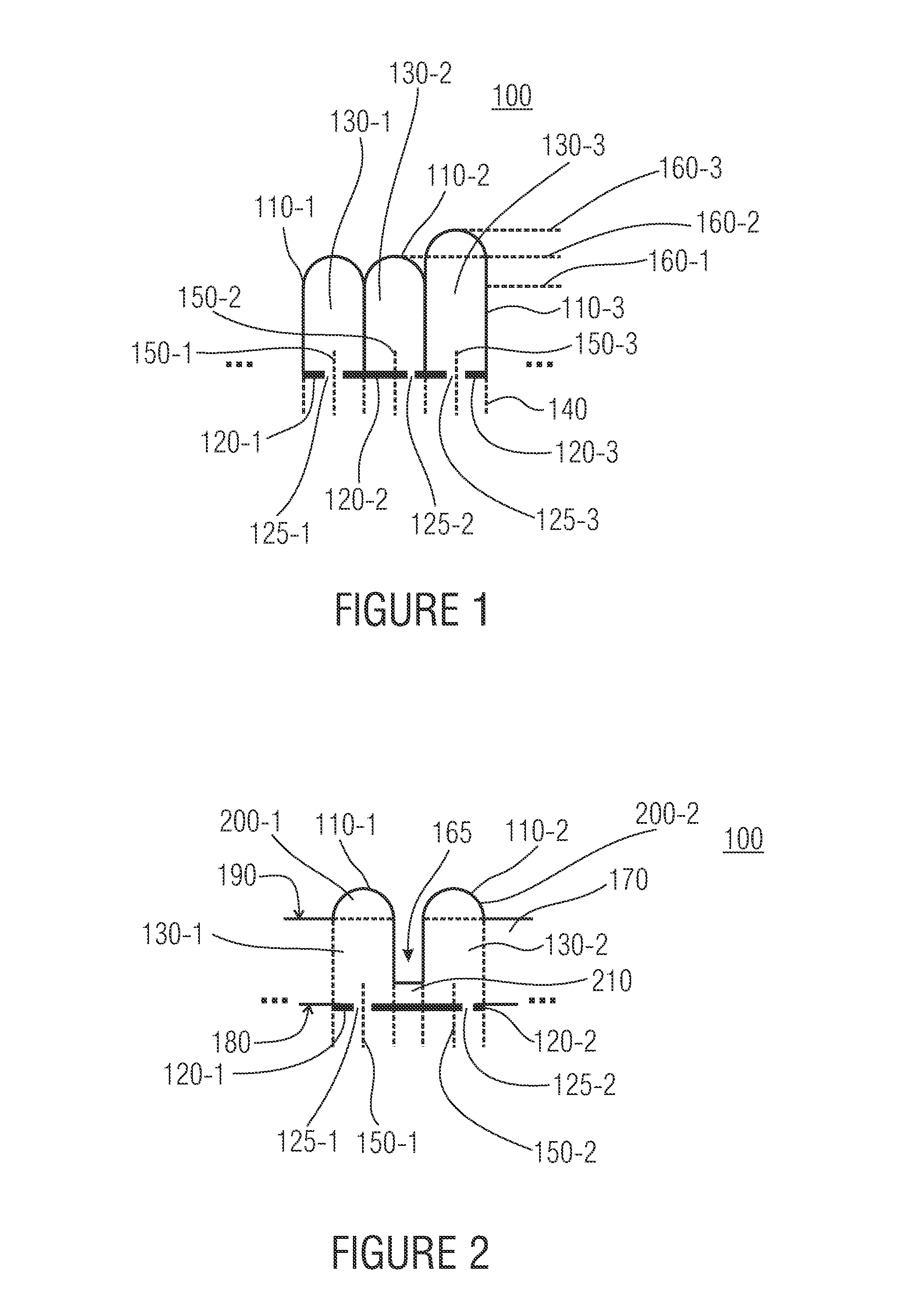
[0042]FIG. 1 shows a beam shaper 100 for a light source arrangement not illustrated in FIG. 1 for generating a radiation profile. Here, the beam shaper 100 comprises a multitude of adjacently arranged optical beam-shaping elements 110, three of which are shown in FIG. 1 in cross-section. The three beam-shaping elements 110-1, 110-2, 110-3 shown in FIG. 1 are of three different types with different optical characteristics. The same are determined by the structural features of the individual beam-shaping...


PUM


Abstract

A beam shaper according to an embodiment of the present invention for a light source arrangement for generating a radiation profile includes a multitude of adjacently arranged optical beam-shaping elements, each belonging to one type of a plurality of different types with different optical characteristics. When illuminated together, the beam-shaping elements effect the radiation profile of the beam shaper and each include an intensity-modulating element and a refractive element.

Description

CROSS-REFERENCE TO RELATED APPLICATIONS[0001]This application is a continuation of copending International Application No. PCT / EP2010 / 054446, filed Apr. 1, 2010, which is incorporated herein by reference in its entirety, and additionally claims priority from German Application No. DE 102009016234.8 filed Apr. 3, 2009, which is incorporated herein by reference in its entirety.BACKGROUND OF THE INVENTION[0002]Embodiments of the present invention relate to beam shapers that are used, for example, in the field of illuminations and projective displays.[0003]In many technical applications, compact illumination means are used nowadays that are, for example, part of a projective display or a projective display element. Here, projection areas associated with the respective device can be used as projection areas, such as a diffusely scattering projection screen, or also external projection areas can be used, for example a (diffusely) scattering wall of a room. Also, respective illuminations a...

Claims


Application Information

Patent Timeline
IPC IPC(8): F21V13/04F21V5/00
CPCG02B3/0043G02B27/0961G02B3/0056
Inventor MICHAELIS, DIRKWAECHTER, CHRISTOPHDANZ, NORBERTKUDAEV, SERGEYFLAEMMICH, MICHAEL
Owner FRAUNHOFER GESELLSCHAFT ZUR FOERDERUNG DER ANGEWANDTEN FORSCHUNG EV
Why Eureka
Try Eureka