System and method for assisting with attachment of a stock implant to a patient tissue

a technology of surgical guide and patient tissue, which is applied in the field of system and method for assisting with the attachment of a stock implant to a patient tissue, can solve the problems of bone deformation, end up deteriorating, and further erosion,

Active Publication Date: 2012-05-03
THE CLEVELAND CLINIC FOUND
View PDF9 Cites 192 Cited by
  • Summary
  • Abstract
  • Description
  • Claims
  • Application Information

AI Technical Summary

Problems solved by technology

Diseases such as rheumatoid- and osteo-arthritis can cause erosion of the cartilage lining of the acetabulum so that the ball of the femur and the hip bone rub together, causing pain and further erosion.
Bone erosion may cause the bones themselves to attempt to compensate for the erosion which may result in the bone becoming deformed.
This misshapen joint may cause pain and may eventually cease to function altogether.
This is particularly important since incorrect positioning of the acetabular cup component can lead to the prosthetic hip joint suffering from dislocations, a decreased range of motion, and possibly eventual loosening and / or failure of one or both components of the joint.
However, despite this known positioning procedure, the orientation of the acetabular cup portion in the replaced hip can deviate from the desired orientation.
As the position to be judged by the user is a compound angle, it may be particularly difficult to visualize.
Second, since the natural face of the acetabulum is not uniform and—where the hip is arthritic—may be distorted by osteophytes, the acetabulum is not generally a reliable guide for orientating the acetabular cup portion of the prosthetic joint.
A third problem is that the prior art mechanical alignment guides usually rely on the pelvis being in a set position which may itself be difficult to judge, particularly in an obese patient.
During surgery, and particularly minimally invasive procedures, the plane of the scapula may be difficult or impossible to determine by direct visual inspection, resulting in the need for assistive devices or methods to define both the pathologic version present at the time of surgery and the intended correction angle.
However, surgical navigation arrangements of this type are not wholly satisfactory since they generally use only a low number of measured landmark points to register the patient's anatomy and to specify the angle of the prosthetic implant component (e.g., a glenoid component), which may not provide the desired level of accuracy.
Further, the information provided by such systems may be difficult to interpret and may even provide the user with a false sense of security.
Moreover, these systems are generally expensive to install and operate and also have high user training costs.
While these trial systems may help with checking whether the selected position is correct, they are not well-suited to specify the correct position initially, and thus there still is user desire for a system which may assist a user in placement of prosthetic implant component in a prepared native tissue site.

Method used


Image

  • System and method for assisting with attachment of a stock implant to a patient tissue
  • System and method for assisting with attachment of a stock implant to a patient tissue
  • System and method for assisting with attachment of a stock implant to a patient tissue

Examples


first embodiment

[0047]To aid with carrying out a preoperative plan for attaching a stock prosthetic implant to a patient tissue, a guide 426 may be provided, according to the present invention. The guide 426, shown in various optional configurations in FIGS. 4-10, is at least partially custom-manufactured for a particular patient responsive to preoperative imaging of the patient tissue. For example, the guide 426 may be wholly custom-made (e.g., using rapid prototyping techniques) or may be modified from a stock guide or guide blank (not shown). It is contemplated that at least a part of the guide 426 is a patient-specific, single-use, bespoke feature suited only for use at the indicated surgical site, though one of ordinary skill in the art could create a guide (not shown) which uses a patient-specific “disposable” structure connected to a stock, generic “reusable” carrier.

[0048]Regardless of the whole / partial custom manufacture status, the guide 426 may be configured responsive to at least one of...

second embodiment

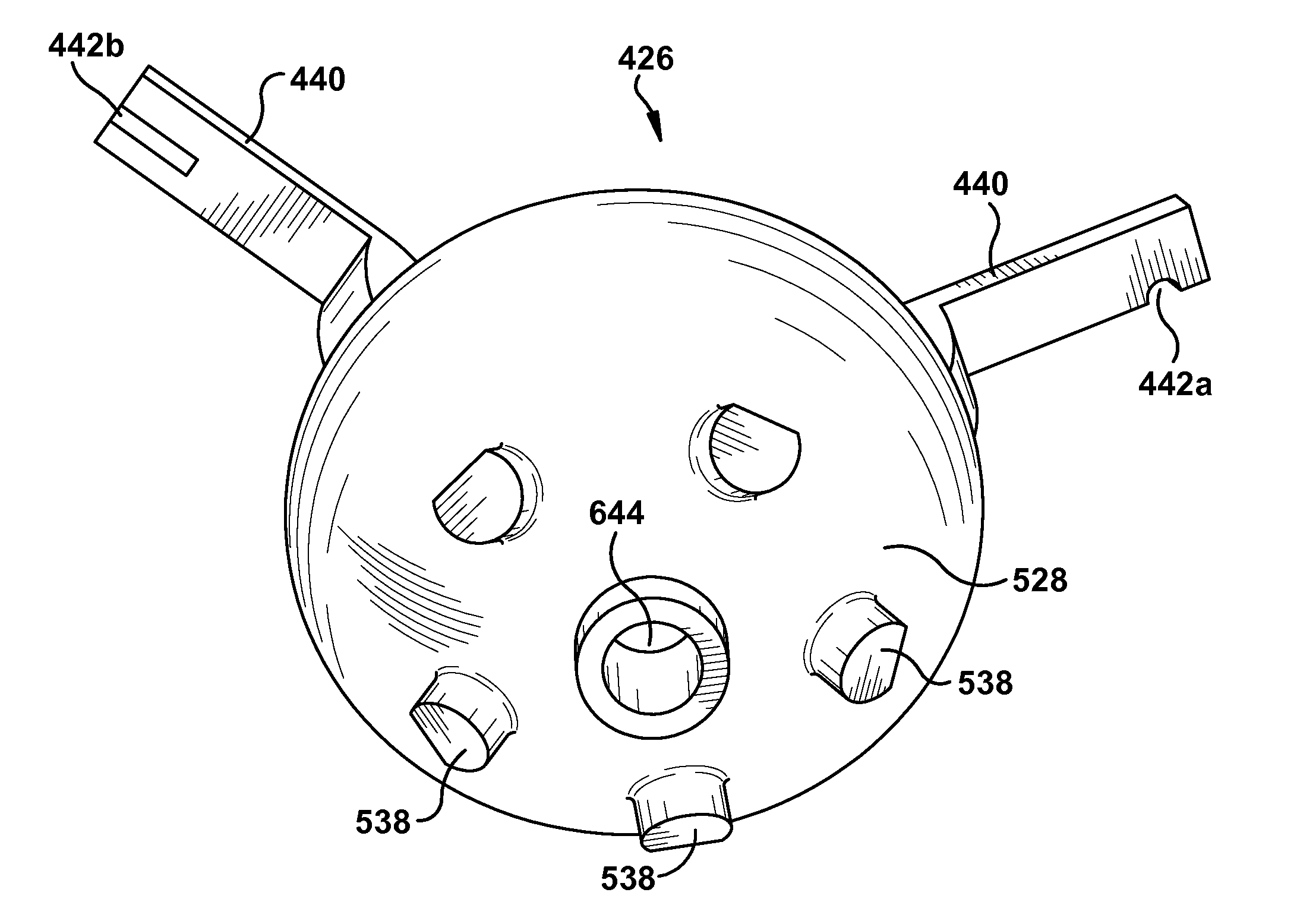
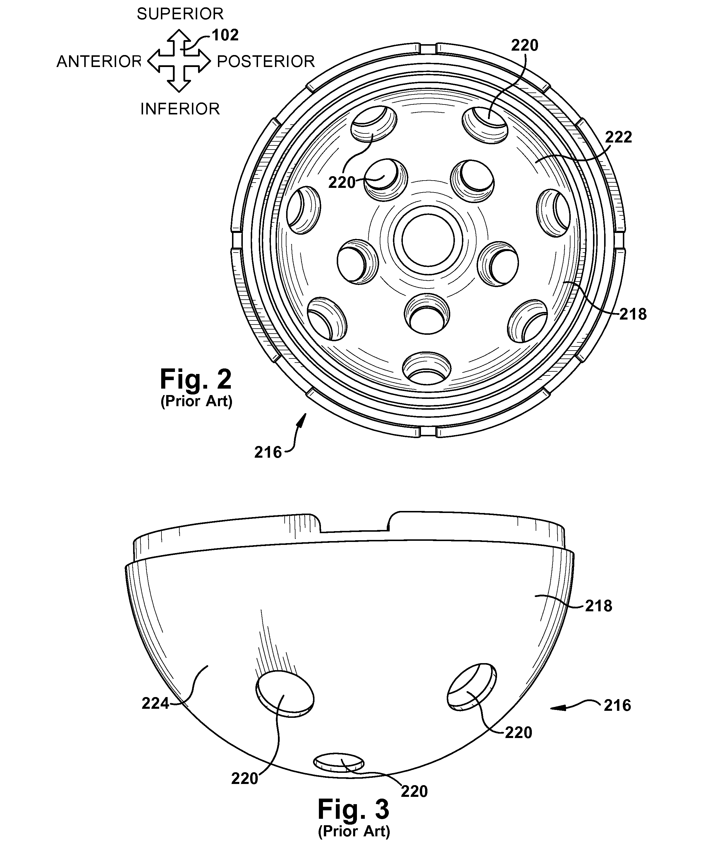
[0088]A guide 426′ for use with the glenoid implant 2364 is shown in FIGS. 25-27. As can be seen in FIG. 26, the guide 426′ includes a central protrusion 2670 configured to nest into the shaft aperture 2368 of the glenoid implant 2364. In the second embodiment, the fastener apertures 220′ of the glenoid implant 2364 also serve to accept the locating protrusions 538′ of the guide 426′, which surround each of the fastener apertures, as shown. The fastener apertures 220′ are optionally countersunk to accept the locating protrusions 538′. When a countersunk fastener aperture 220′ is provided for a locating protrusion 538′, whether the countersunk feature is added by the user or originally provided by the implant manufacturer, the countersunk portion might also or instead be used to accept a fastener head 2160′ to provide a smooth upper implant surface 222′ with no protruding fastener heads when securement of the glenoid implant 958 to the patient tissue is complete. With reference to FI...


PUM


Abstract

A guide for assisting with attachment of a stock prosthetic implant to a patient tissue includes a lower guide surface configured to contact an upper implant surface of the stock prosthetic implant when a lower implant surface of the stock prosthetic implant contacts the patient tissue. An upper guide surface is accessible to a user when the lower guide surface is in contact with the upper implant surface. At least one guiding aperture extends through the guide body between the upper and lower guide surfaces at a predetermined aperture location with respect to the guide body and defines a predetermined target trajectory through the guide body. At least one of the target trajectory and the aperture location of each guiding aperture is preselected responsive to preoperative imaging of the patient tissue. A method of assisting with attachment of a stock prosthetic implant to a patient tissue is also provided.

Description

RELATED APPLICATION[0001]This application claims priority from U.S. Provisional Application No. 61 / 408,324, filed Oct. 29, 2010, the subject matter of which is incorporated herein by reference in its entirety.TECHNICAL FIELD[0002]The present invention relates to a system and method for use of a surgical guide and, more particularly, to a system and method for use of a surgical guide for assisting with attachment of a stock implant to a patient tissue.BACKGROUND OF THE INVENTION[0003]The efficient functioning of the hip joints is important to the well-being and mobility of the human body. Each hip joint includes the upper portion of the femur, which terminates in an offset bony neck surmounted by a ball-headed portion known as the femoral head. The femoral head rotates within a socket, known as the acetabulum, in the pelvis to complete the hip joint. Diseases such as rheumatoid- and osteo-arthritis can cause erosion of the cartilage lining of the acetabulum so that the ball of the fe...

Claims


Application Information

Patent Timeline
Patent Type & Authority Applications(United States)
IPC IPC(8): A61B17/56
CPCA61B17/1728A61F2002/4687A61B17/8061A61B17/8897A61B2017/00526A61B2017/568A61B2017/90A61F2/34A61F2/4609A61F2002/3401A61F2002/3403A61F2002/3408A61B17/1753A61B34/10A61B17/1778A61B17/1746A61B17/90
Inventor IANNOTTI, JOSEPH P.BARSOUM, WAEL K.BRYAN, JASON A.
Owner THE CLEVELAND CLINIC FOUND
Why Eureka
Try Eureka