This helps you quickly interpret patents by identifying the three key elements:
Problems solved by technology
Method used
Benefits of technology
Benefits of technology
[0008]The present disclosure is to provide a linear vibrator configured to reduce both thickness and superficial area by horizontally reciprocating a magnet and a weight inside a case to generate vibration, whereby vibration power can be increased to reduce an overall size of the vibrator.
Problems solved by technology
However, in the vertical linear vibrator that vertically reciprocates the magnet and the magnet inside the case to generate vibration, a space for vibrating the spring is needed because the spring is vertically driven to generate the vibration, whereby thickness and volume increase to disadvantageously increase thickness and volume of electronic products and living products in which the vertical linear vibrator is mounted.
Method used
Image
Click on the blue label to locate the original text in one second.
Reading with bidirectional positioning of images and text.
Examples
first exemplary embodiment
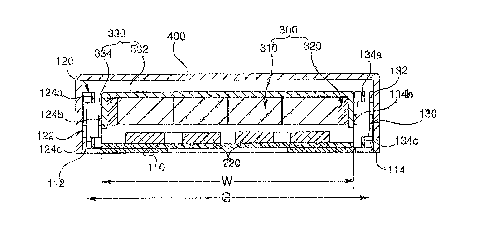
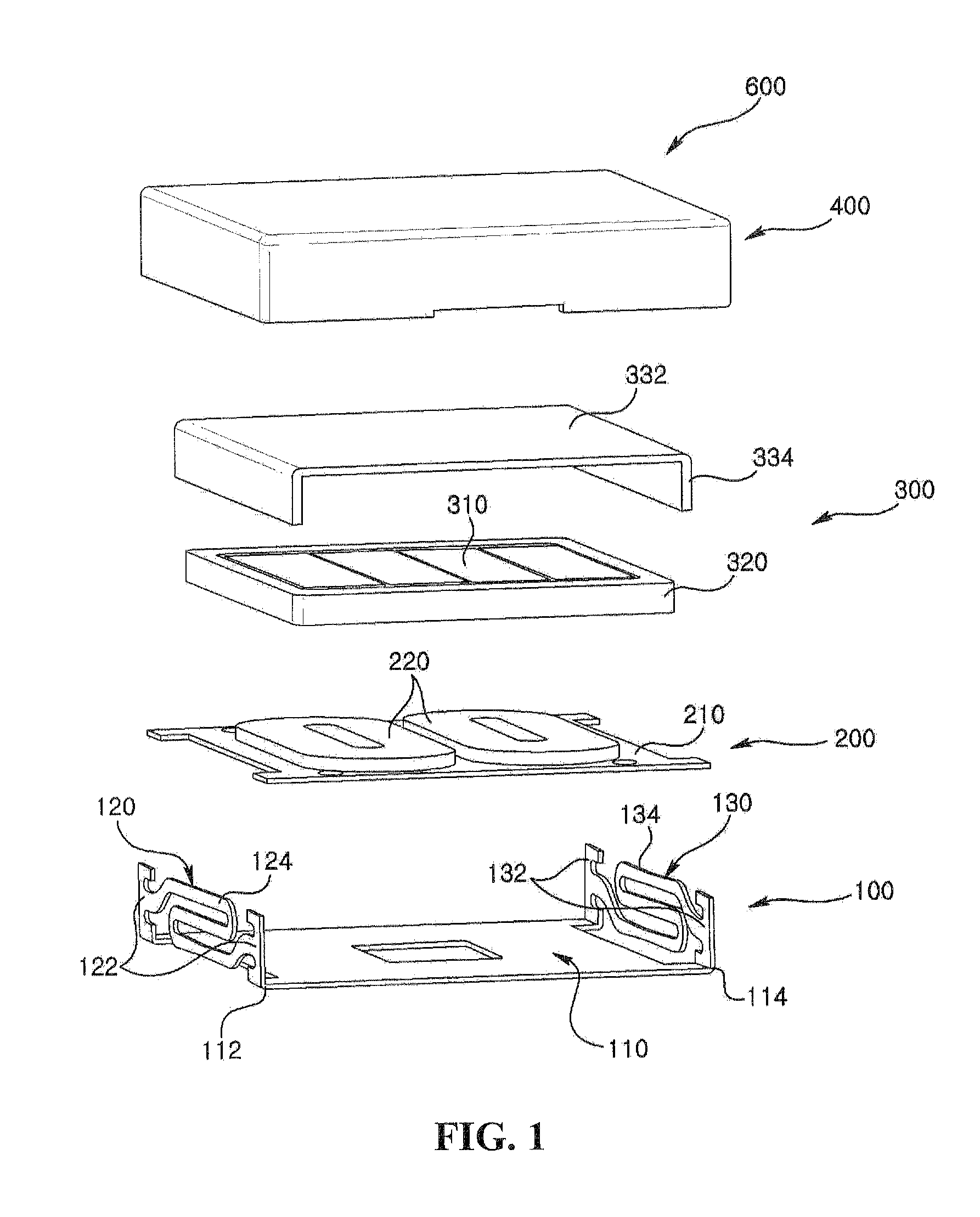
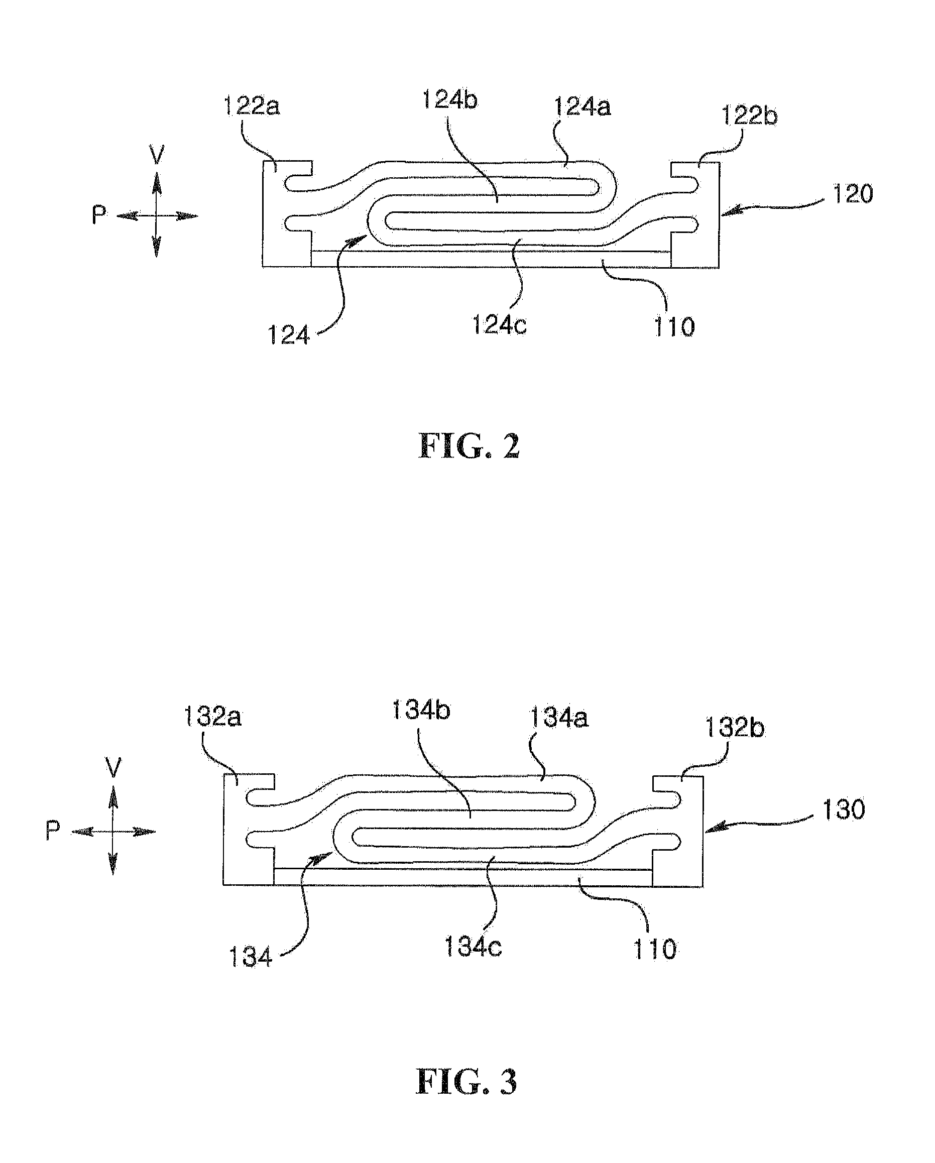
[0025]FIG. 1 is an exploded perspective view of a linear vibrator according to a first exemplary embodiment of the present disclosure, FIG. 2 is a front view of a first elastic unit of FIG. 1, FIG. 3 is a front view of a second elastic unit of FIG. 1, FIG. 4 is a schematic assembled cross-sectional view of a liner vibrator of FIG. 1, and FIG. 5 is a plane view of a linear vibrator except for an upper case of FIG. 1.
[0026]Referring to FIGS. 1 to 5, a linear vibrator (600) includes a bottom case (100), a stator (200), a trembler (300) and an upper case (400).
[0027]The bottom case (100) may be formed by processing a metal plate, for example. The bottom case (100) includes a floor plate (110), a first elastic unit (120) and a second elastic unit (130). In the embodiment of the present disclosure, the floor plate (110), the first elastic unit (120) and the second elastic unit (130) may be integrally formed.
[0028]The floor plate (110) is formed in the shape of a plate. In the embodiment o...
second exemplary embodiment
[0066]FIG. 8 is a cross-sectional view illustrating a linear vibrator according to a second exemplary embodiment of the present disclosure.
[0067]A linear vibrator illustrated in FIG. 8 is substantially same as that of the linear vibrator illustrated in FIGS. 1 to 7 except for positions of the first and second elastic units. Thus, redundant description as that of FIGS. 1 to 7 will be omitted, and if considered appropriate, reference numerals have been repeated among the figures to indicate corresponding and / or analogous elements.
[0068]Referring to FIG. 8, a linear vibrator (600) includes a bottom case (100), a stator (200), a trembler (300) and an upper case (400) including first and second elastic units (430, 440).
[0069]The upper case (400) includes an upper plate (410), a lateral surface plate (420), and first and second elastic units (430, 440).
[0070]In a non-limiting example, the upper plate (410) takes the shape of a rectangular plate, and the lateral surface plate (420) is exte...
PUM
Abstract
Disclosed is a linear vibrator, the linear vibrator including: a bottom case including a floor plate and first and second elastic units integrally formed with the floor plate, and mutually and oppositely bent from both distal ends facing the floor plate; a stator including a circuit substrate arranged on the floor plate and a coil block electrically connected to the circuit substrate; a trembler including a magnet discretely facing the coil block and a weight securing the magnet; and an upper case coupled to the bottom case to accommodate the stator and the trembler, wherein both lateral surfaces of the trembler facing the first and second elastic units are elastically supported by the first and second elastic units.
Description
CROSS-REFERENCE TO RELATED APPLICATIONS[0001]This application claims the benefit under 35 U.S.C. §119 of Korean Patent Application Nos. 10-2010-0111729, filed. Nov. 10, 2010, and 10-2010-0111730, filed Nov. 10, 2010, which are hereby incorporated by reference in their entirety.BACKGROUND OF THE DISCLOSURE[0002]1. Field of the Disclosure[0003]The present disclosure relates to a linear vibrator.[0004]2. Description of the Related Art[0005]A linear vibrator is applied to various electronic devices, such as mobile phones, game players, mobile game players, game controllers and joy sticks, and electric tooth brushes, to generate vibration.[0006]The linear vibrator generally includes a case including a bottom case and an upper case, a coil secured to the bottom case, a magnet arranged about or inside the coil, a weight securing the magnet, and a spring such as a leaf spring or a coil spring reciprocating the weight and the magnet from a upper case direction to a bottom case direction. The...
Claims
Application Information
Patent Timeline
Application Date:The date an application was filed.
Publication Date:The date a patent or application was officially published.
First Publication Date:The earliest publication date of a patent with the same application number.
Issue Date:Publication date of the patent grant document.
PCT Entry Date:The Entry date of PCT National Phase.
Estimated Expiry Date:The statutory expiry date of a patent right according to the Patent Law, and it is the longest term of protection that the patent right can achieve without the termination of the patent right due to other reasons(Term extension factor has been taken into account ).
Invalid Date:Actual expiry date is based on effective date or publication date of legal transaction data of invalid patent.

