MRI Safety System

a safety system and magnetic field technology, applied in the field of magnetic field safety system, can solve the problems of current system being vulnerable to human error, ferromagnetic objects which may become hazardous, and potential hazards, and achieve the effects of reducing the size of the sensor node, and reducing the risk of ferromagnetic objects becoming hazardous

Active Publication Date: 2012-05-10
DEERFIELD IMAGING INC
View PDF19 Cites 37 Cited by
  • Summary
  • Abstract
  • Description
  • Claims
  • Application Information

AI Technical Summary

Benefits of technology

[0091]The system using the central controller avoids having to rely on manual control of related systems is inconvenient to the user and introduces the possibility of manual error. For example, a competing system could require that as the field values change, the user manually opens the RF door which is less convenient.
[0092]The arrangement therefore provides a new magnetic field monitoring system that monitors potential safety hazards via a wireless sensor network. This systems provides an output signal for a central alarm and has configurable alarm thresholds. Use of such a system supplements existing practices and enables further enhancement to room control systems to accommodate custom workflows.
[0093]The sensor network consists of a PC interface, a base station and multiple sensor nodes. A sensor evaluation board is used to compare measurement performance of giant magneto-resistive (GMR) sensors to Hall effect sensors. Hall effect sensors are selected based on lower current draw (sleep and active modes) and larger measurement range. This design is implemented on a custom printed circuit board (FIG. 2). Main sensor components include: power supply, Hall effect sensors, anti-aliasing filters, microcontroller (PIC18F, Microchip) and RF module (MRF24J40MA, Microchip). In monitoring mode, the microcontroller queries the Hall effect sensors sequentially. The magnetic field magnitude is compared to software-set thresholds (5G, 50G) that represent alarm conditions. The RF module uses the IEEE 802.15.4 based MiWi P2P protocol operating in the 2.4 GHz ISM band. The protocol is suitable for low-power and low-data rate applications. A further design effort reduced the size of the sensor nodes (FIG. 3). Both bench and lab testing are performed. The lab tests are performed on a movable 1.5T Siemens Espree scanner (IMRIS, Winnipeg). Tests included: communication in a reflective environment, communication range, round-trip communication latency, communication rate, network collision frequency, node wake up time, and alarm conditions. A standard Siemens RF noise test (with phantom) is also conducted with the system in operation.
[0094]Testing revealed that magnetic field measurements of the sensor system are in agreement with a magnetometer (average 1.71G; std dev 0.75G; range −3G to 2G). The Siemens RF test showed an elevated baseline signal intensity but no image artifacts. A magnetic field saturation test showed that the Hall effect sensors and device continued to operate normally after being placed at scanner isocentre for a brief period.

Problems solved by technology

However, this beneficial new technology creates potential hazards which do not exist in traditional MRI systems.
These hazards are due to the fact that MRI employs extremely strong magnetic fields of up to 3 tesla in a clinical setting; more than enough to turn a ferromagnetic object into a dangerous projectile.
Surgery being performed in an operating room often requires ferromagnetic objects which may become hazardous once an MRI system enters the room.
This current system is vulnerable to human error and does not monitor the source of the hazard, the presence of a strong magnetic field.
However, existing audible magnetic field sensors are fairly large in size and cannot be easily mounted to third party equipment.
Furthermore, these sensors work individually using local audio alarm, are designed for larger structures and provide a limited number of alarm thresholds.
In summary, to date there has been a lack of integration between computer-based checklists, room control systems and miniaturized distributed magnetic field sensors.
When a movable MRI scanner is used intra-operatively, there are safety concerns and impacts to the existing workflow.
Materials that are attracted to magnets (ferromagnetic) may become projectiles causing injury or death to the patient, to hospital staff or to the surgeons.

Method used


Image

  • MRI Safety System
  • MRI Safety System
  • MRI Safety System

Examples


Embodiment Construction

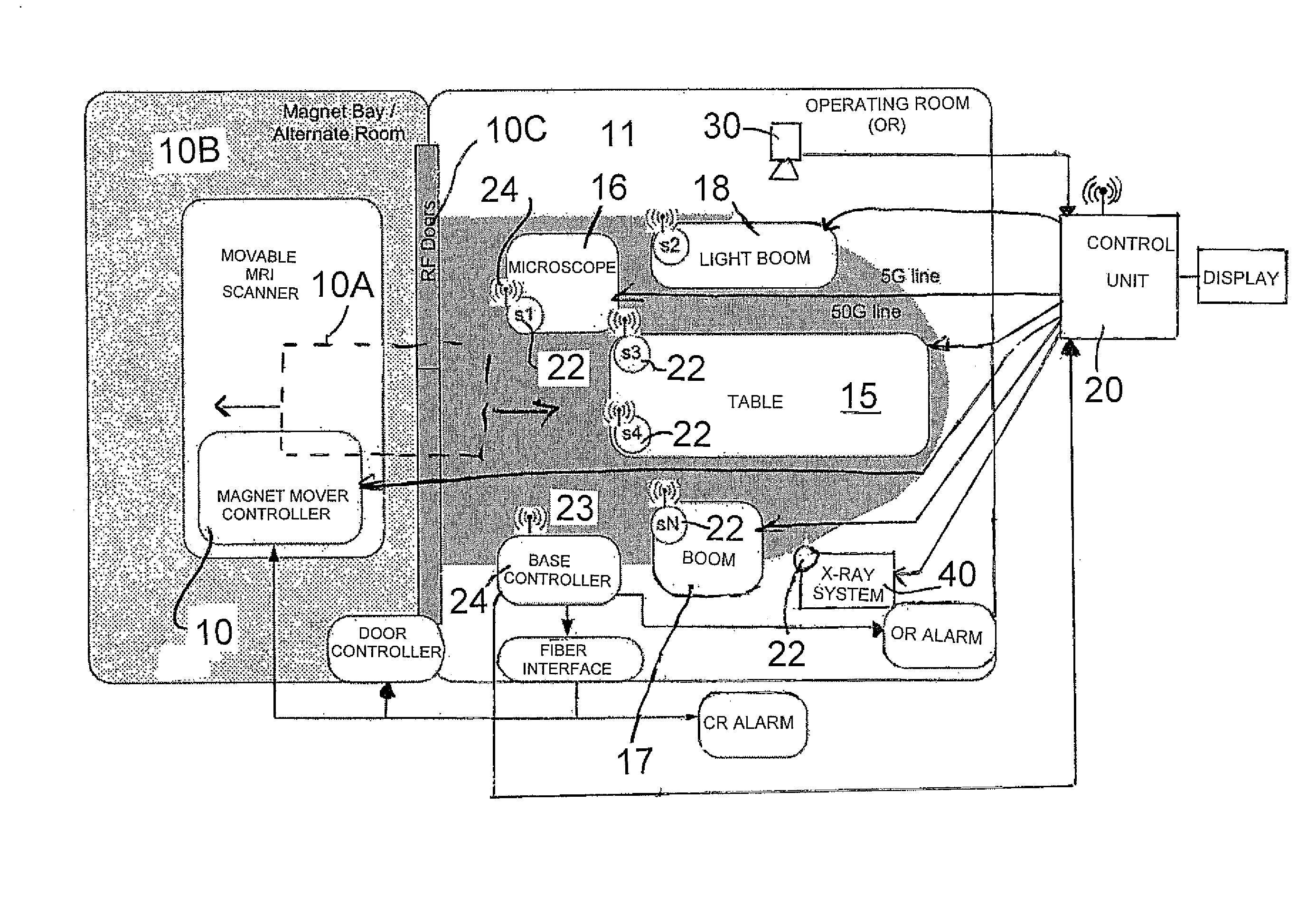
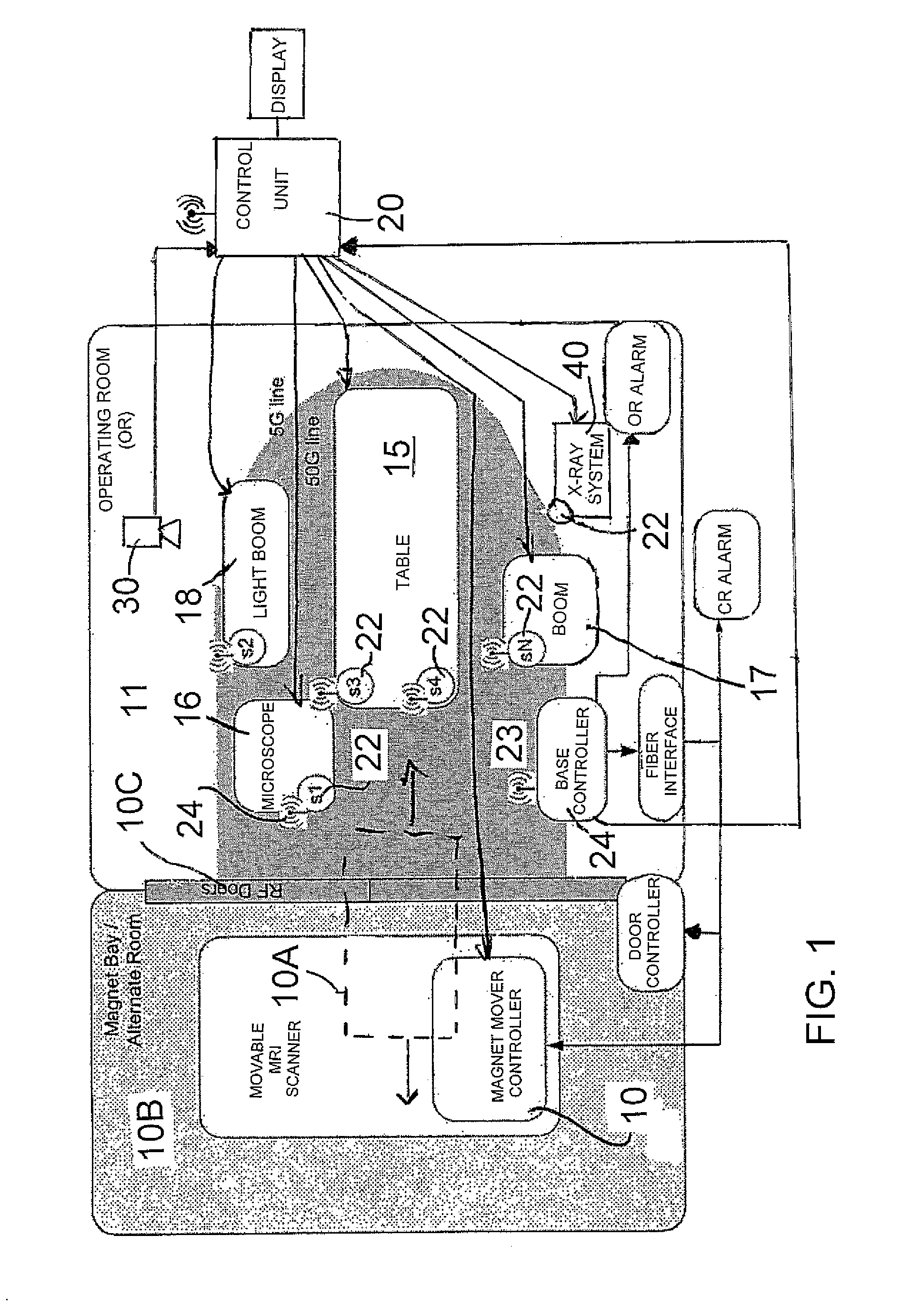
[0108]The apparatus for carrying out medical procedures on a patient as used in the present invention includes a magnetic resonance imaging apparatus 10 of a conventional construction well known to persons skilled in this field. The system includes a magnet 10A for generating a magnetic field of sufficient intensity to carry out a magnetic resonance imaging procedure on the patient. This is associated with RF coils and gradient coils together with the control systems for operating these components which are not the subject of the present invention and thus will not be described in detail.

[0109]In the arrangement with which the present invention is concerned, the magnet 10A is movable between a magnet bay area 10B and an operating room 11. The room 11 may form one of a suite of rooms arranged around the bay 10B and into which the magnet 10A may move through doors 10C.

[0110]The magnet cooperates with a table 15 on which the patient is positioned for the imaging process. The table can ...


PUM


Abstract

In a MRI system housed within a room there is provided a movable magnet and additional components for other procedures on the patient, a control system is provided for the relative movement of the magnet and components. This includes a plurality of magnetic field sensors mounted on the components for measuring the magnetic field at the location of the component and an optional camera positioning system so that the control system can estimate relative positions of the components relative to the magnet from the sensed field strengths from the set of sensors to avoid collisions during the movements.

Description

[0001]This invention relates to a safety control system in an apparatus for carrying out medical procedures on a patient where some of the components are movable.[0002]This system has applications in for use in operating rooms equipped with a high field intra-operative movable MRI scanner.BACKGROUND OF THE INVENTION[0003]Recent innovations in Magnetic Resonance Imaging (MRI) technology has allowed IMRIS to develop new inter-operative imaging techniques which allow a patient to be imaged while undergoing surgery in an operating room. This is done by bringing an MRI system into the operating room along ceiling mounted rails at a rate of up to 6.4 cm / second. The technology has the advantage of giving surgeons immediate feedback for an ongoing operation which they did not previously have access to. However, this beneficial new technology creates potential hazards which do not exist in traditional MRI systems. These hazards are due to the fact that MRI employs extremely strong magnetic f...

Claims


Application Information

Patent Timeline
Patent Type & Authority Applications(United States)
IPC IPC(8): G01R33/48
CPCG01R33/288
Inventor ALEXIUK, MARKFALLAH-RAD, MEHRANSCARTH, GORDONHUSHEK, STEPHEN G.CHAMPAGNE, KIRK MAURICEHOEPPNER, TIMOTHY JAMESWEBER, DAVID JOHN ROBERT
Owner DEERFIELD IMAGING INC
Why Eureka
Try Eureka