Ground Fault Detection and Location System and Method for Motor Drives

a technology of ground fault and location system, which is applied in the field of motor drives, can solve the problems of affecting the repair process, and presenting other hazards, and achieves the effect of improving decision-making and increasing the speed with which equipment can be repaired

Active Publication Date: 2012-05-10
ROCKWELL AUTOMATION TECH
View PDF5 Cites 59 Cited by
  • Summary
  • Abstract
  • Description
  • Claims
  • Application Information

AI Technical Summary

Benefits of technology

[0005]The present invention provides a ground fault detection system that may detect ground faults when there is high resistance grounding and which may further identify the location of the ground fault not only with respect to the particular drive affected, but also with respect to a particular side of the DC bus of the motor drive and / or between the motor drive and the wiring to, or windings of, the motor itself or in the AC bus to which the drive is attached. These latter distinctions can permit improved decision-making about remedial steps and increase the speed with which equipment can be repaired.
[0007]It is thus a feature of at least one embodiment of the invention to permit rapid localization of ground faults that may or may not cause failure of the motor drive or motor.
[0011]It is thus a feature of at least one embodiment of the invention to quickly identify ground faults outside of the motor drive.
[0015]It is thus a feature of at least one embodiment of the invention to provide a compact current sensing structure that is more sensitive to current imbalances.
[0021]It is thus a feature of at least one embodiment of the invention to permit rapid and precise identification of ground faults in high resistance grounds systems.

Problems solved by technology

Ground faults in high-powered equipment can produce high current flow into ground of a magnitude that can damage the equipment or present other hazards.
By the same token high resistance grounding can make it difficult to determine that a ground fault has occurred and / or to pinpoint the particular device having a ground fault.
Even when the particular motor drive affected is identified, it may be difficult or impossible to determine the location of the ground fault and the appropriate response.

Method used


Image

  • Ground Fault Detection and Location System and Method for Motor Drives
  • Ground Fault Detection and Location System and Method for Motor Drives
  • Ground Fault Detection and Location System and Method for Motor Drives

Examples


Embodiment Construction

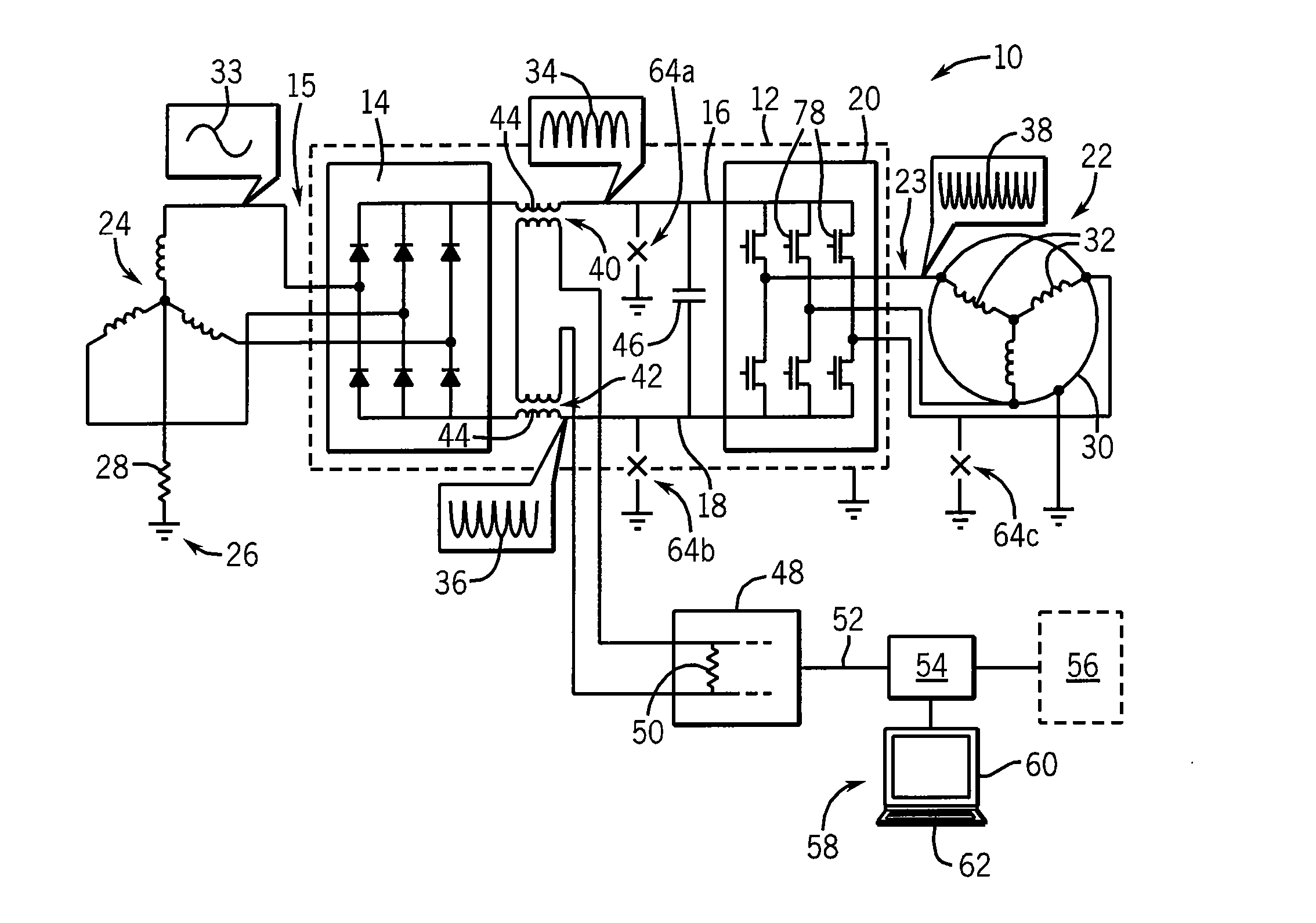
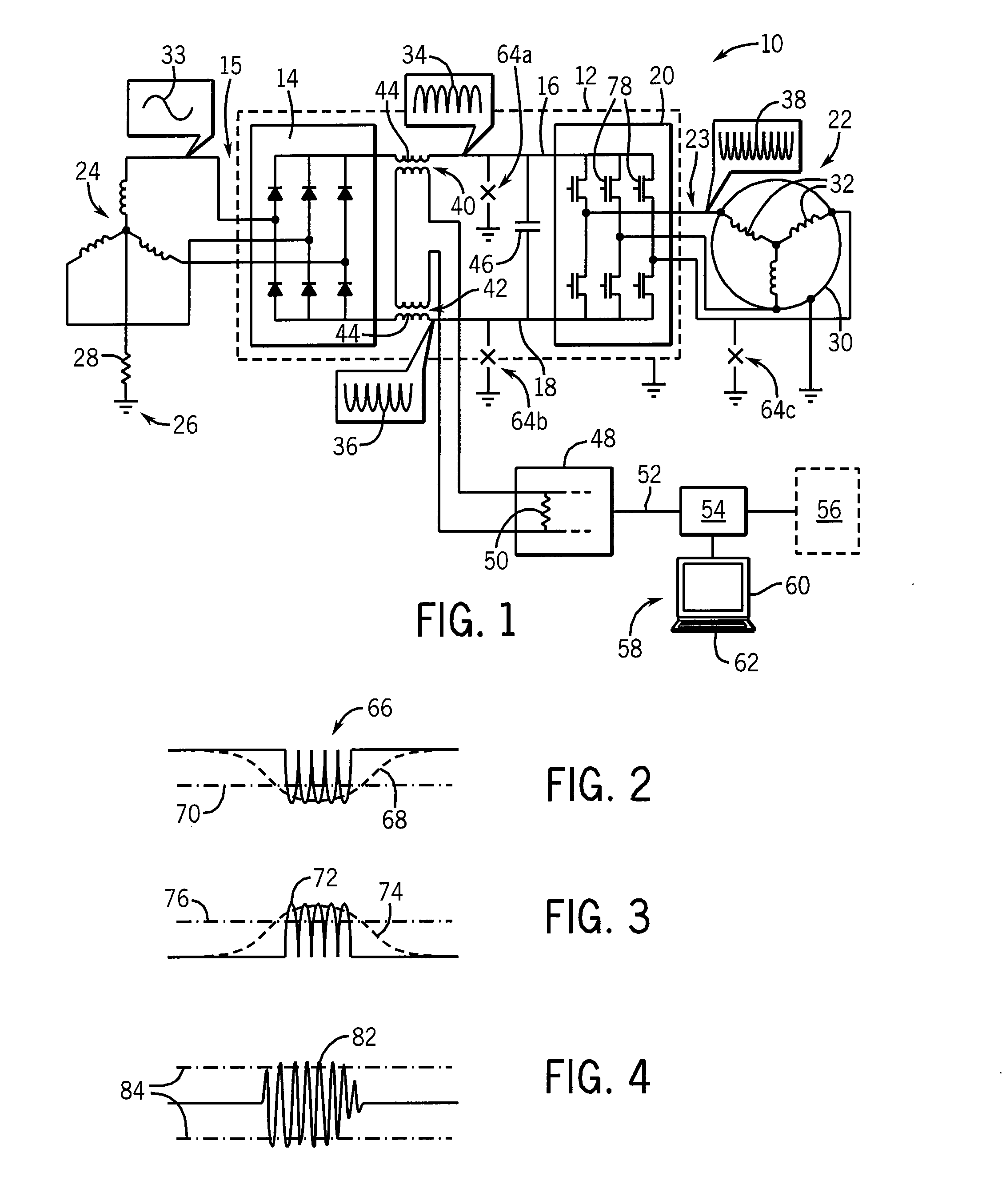
[0037]Referring now to FIG. 1, a motor drive system 10 per the present invention may provide for a housing 12 holding a rectifier unit 14 receiving, for example, three phase power 15 over three input leads 17. The rectifier unit 14 outputs DC power on a positive DC bus conductor 16 and a negative DC bus conductor 18. The DC bus conductors 16 and 18 are then received by an inverter 20 which, under the control of a motor control circuit (not shown), synthesizes new three phase power 23 provided to a motor 22 over three output leads.

[0038]An outer casing 30 of the motor 22 and the housing 12 may be conductive and connected to ground 26 so as to provide a safe path of conduction of ground fault currents, for example, caused by dislodgment of powered internal motor windings 32 that contact the casing 30 or powered conductors inside the motor drive systems 10 that short-circuit to the housing 12.

[0039]The magnitude of such ground fault currents may be limited by a series resistance 28, co...


PUM


Abstract

A motor drive system provides for analysis of current flow in the DC bus to identify ground faults and their locations. Low-frequency positive polarity and negative polarity current differences indicate ground faults from the positive DC bus and negative DC bus respectively. High-frequency signals indicate ground faults in the motor windings and connecting leads.

Description

BACKGROUND OF THE INVENTION[0001]The present invention relates to motor drives and in particular to a ground fault detection system identifying locations of ground faults in motor drive systems.[0002]Motor drive systems provide control of power applied to a motor for improved motor control and efficiency. Generally, such systems receive a source of alternating current (AC) which is rectified to provide a direct current (DC) bus. The DC voltage of the bus is then received by an inverter which synthesizes new AC waveforms to be applied to the motor. The new waveforms, for example, may provide a variable control frequency for regulating the speed of the motor or for controlling its torque or dynamic characteristics such as startup and slowdown.[0003]The circuitry of the motor drives and the windings of motors attached to the motor drives are typically each enclosed in grounded metal housings. Should a powered conductor of either break free and contact the housing, the power of the cond...

Claims


Application Information

Patent Timeline
Patent Type & Authority Applications(United States)
IPC IPC(8): G01R31/14
CPCG01R31/025G01R31/42G01R31/343G01R31/52
Inventor VRANKOVIC, ZORAN V.WEI, LIXIANGSKIBINSKI, GARY L.WINTERHALTER, CRAIG R.
Owner ROCKWELL AUTOMATION TECH
Why Eureka
Try Eureka