
A/d converter circuit, electronic apparatus and a/d conversion method

a converter circuit and electronic equipment technology, applied in the field of a/d converter circuits, electronic equipment, and a/d conversion methods, can solve the problems of reducing the dynamic range of a/d conversion, circuits to become larger in scale, and generation of missing codes, so as to inhibit the reduction of the dynamic range and improve the a/d conversion characteristic

Active Publication Date: 2012-05-10
SEIKO EPSON CORP
View PDF5 Cites 24 Cited by
  • Summary
  • Abstract
  • Description
  • Claims
  • Application Information

AI Technical Summary

Benefits of technology

[0007]In accordance with an advantage of some aspects of the invention, it is possible to provide A / D converter circuits, electronic apparatuses and A / D conversion methods that can improve the A / D conversion characteristic and can inhibit a reduction in the dynamic range.

Problems solved by technology

This causes the circuit to become larger in scale.
However, this may lead to problems, such as, generation of missing codes, due to errors of differential nonlinearity (DNL), integral nonlinearity (INL) and the like.
The A / D conversion characteristic such as DNL and INL may be improved, but such improvement may reduce the dynamic range in A / D conversion.
This is not desirable for the performance required for A / D conversion.

Method used


Image

  • A/d converter circuit, electronic apparatus and a/d conversion method
  • A/d converter circuit, electronic apparatus and a/d conversion method
  • A/d converter circuit, electronic apparatus and a/d conversion method

Examples


Embodiment Construction

[0060]Preferred embodiments of the invention will be described below in detail. It is noted that the embodiments described below will not unduly limit the contents of the invention recited in claims, and all of the configurations to be described in the embodiments would not necessarily be indispensable as the means for solution provided by the invention.

[0061]1. Configuration

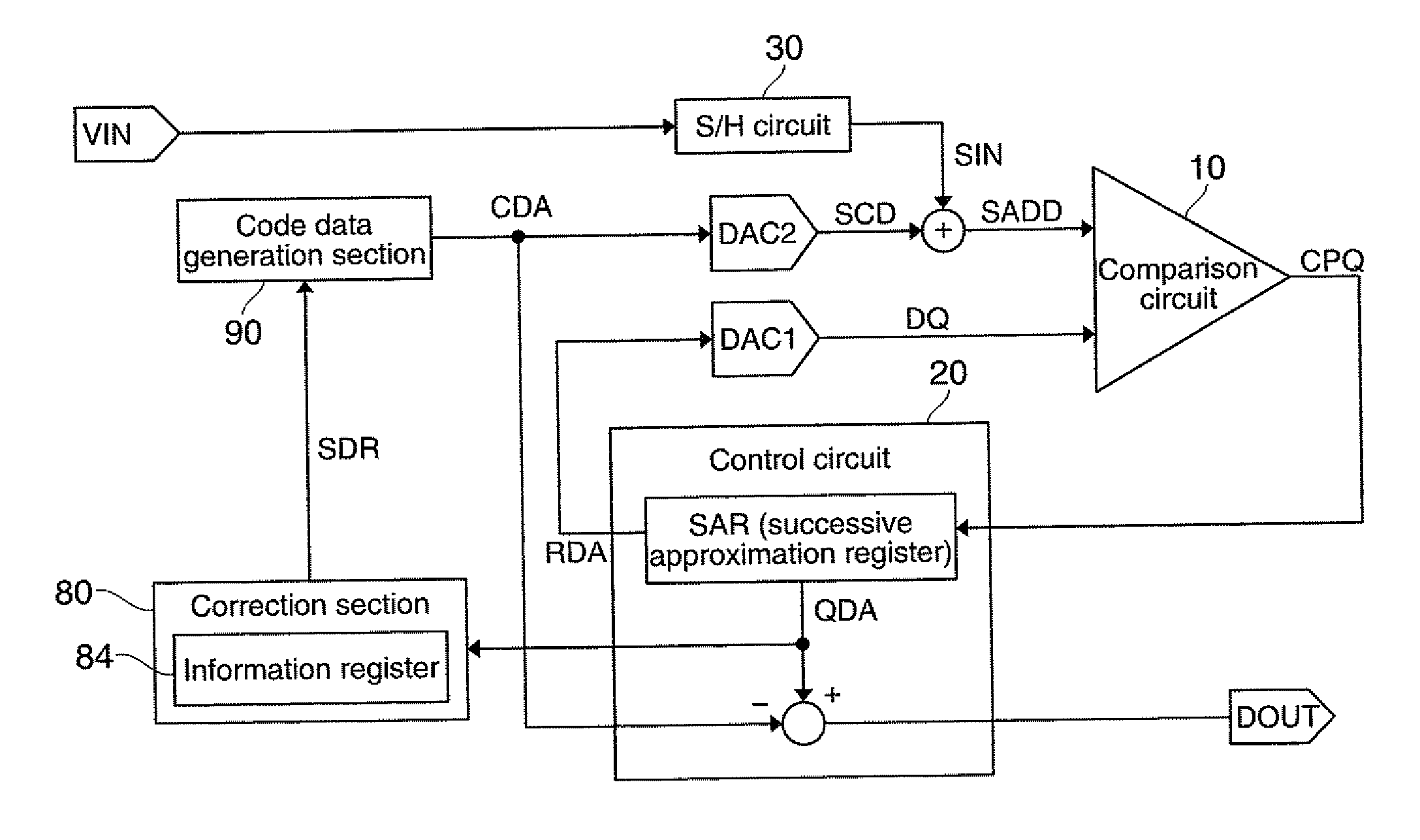
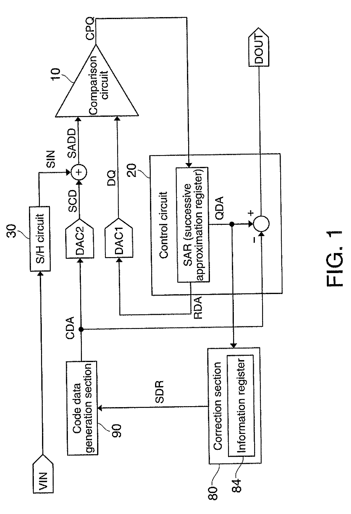
[0062]FIG. 1 shows an exemplary configuration of an A / D converter circuit in accordance with an embodiment of the invention. The A / D converter circuit includes a comparison circuit 10, a control circuit 20, a first D / A converter circuit DAC1, a second D / A converter circuit DAC2 and a correction section 80. The A / D converter circuit may also be provided with a sample and hold (S / H) circuit 30 and a code data generation section 90.

[0063]It is noted that the A / D converter circuit of the present embodiment is not limited to the configuration shown in FIG. 1, but various modifications, such as, omission of a part of ...


PUM


Abstract

An A / D converter circuit includes a comparison circuit that performs a process to compare an added signal of a sampled signal of an input signal and a code signal with a D / A output signal, or a process to compare the sampled signal with an added signal of the D / A output signal and the code signal, a control circuit that outputs output data obtained based on successive approximation result data and the code data as A / D conversion data of the input signal, a first D / A converter circuit that D / A converts the data for successive approximation, a second D / A converter circuit that D / A converts code data that changes over time, and a correction section that performs a correction process, to correct the successive approximation result data so as not to overflow due to code shifting using the code data.

Description

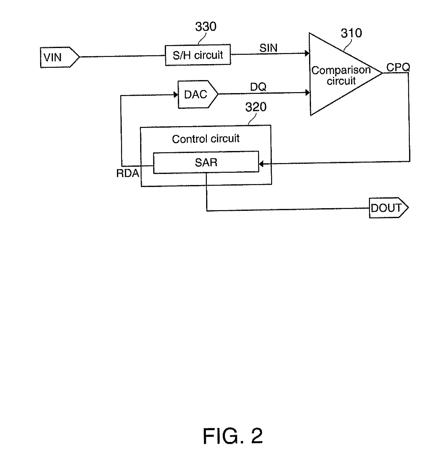
BACKGROUND[0001]1. Technical Field[0002]The present invention relates to A / D converter circuits, electronic apparatuses, and A / D conversion methods.[0003]2. Related Art[0004]As an A / D converter circuit that converts an analog signal to digital data, a successive approximation A / D converter circuit is known. The successive approximation A / D converter circuit is typically equipped with a comparison circuit, a successive approximation register, and a D / A converter circuit, and performs analog-to-digital conversion of a sampled signal (a sampled and held signal) of an input signal by the successive approximation operation to thereby output digital data. As one of the common implementations of the successive approximation A / D converter circuit, the technology described in Japanese Laid-open Patent Application HEI 08-321779 (Patent Document 1) is known.[0005]The conversion accuracy of such an A / D converter circuit mostly depends on the accuracy of the D / A converter circuit. When increasin...

Claims


Application Information

Patent Timeline
IPC IPC(8): H03M1/38
CPCH03M1/12H03M1/38H03M1/468H03M1/1019
Inventor HANEDA, HIDEO
Owner SEIKO EPSON CORP
Learn More