

Imaging apparatus, imaging system, and control method thereof
- Summary
- Abstract
- Description
- Claims
- Application Information
AI Technical Summary
Benefits of technology
Problems solved by technology
Method used
Image

Examples
Embodiment Construction
[0022]Various exemplary embodiments, features, and aspects of the invention will be described in detail below with reference to the drawings.
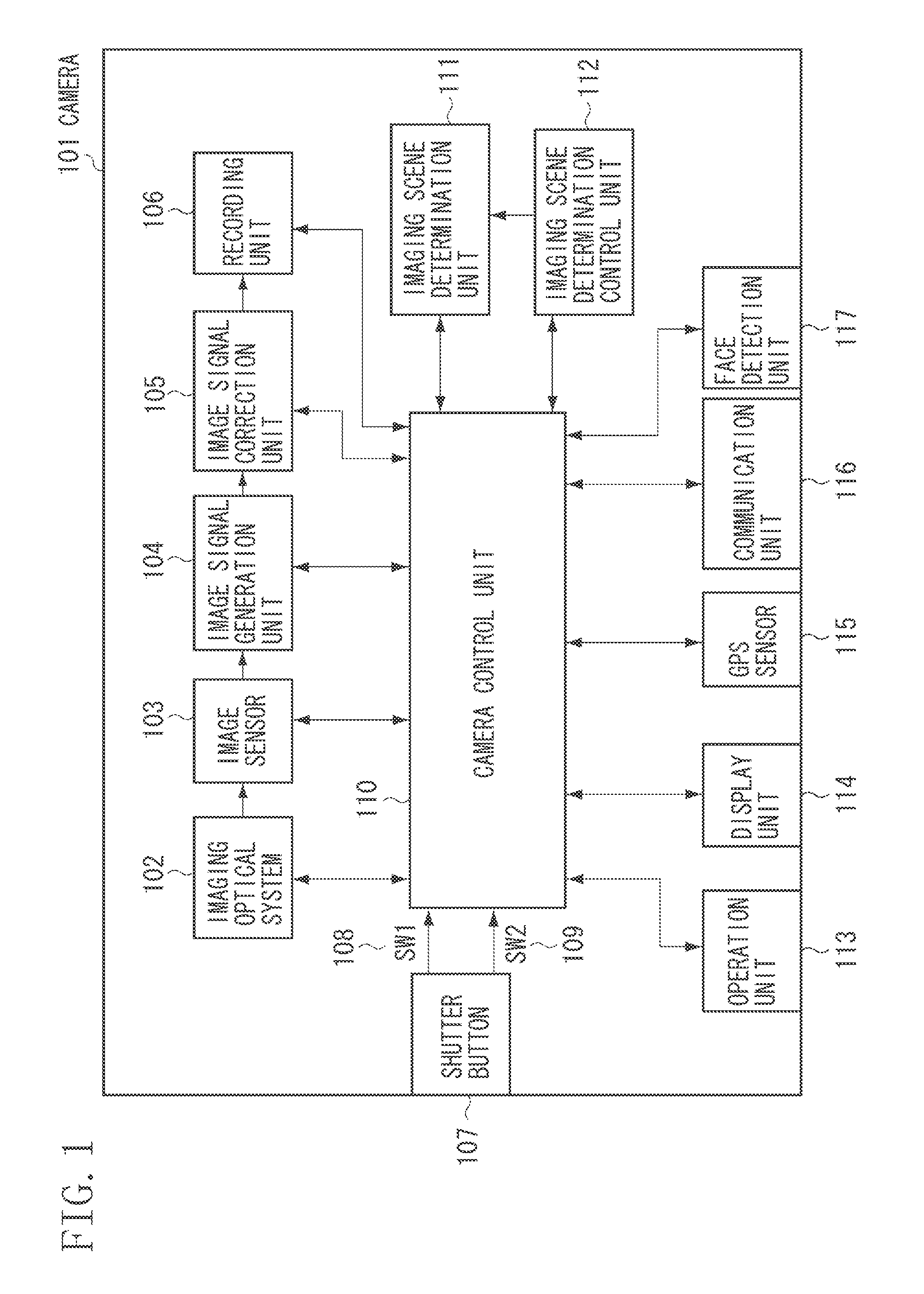
[0023]In an exemplary embodiment of the present invention, an example imaging system using a digital camera including an imaging apparatus is described. Herein, imaging scenes includes five types of imaging scenes such as a “portrait” for imaging a scene including a person, a “sunset sky” for imaging a scene including a sunset sky, a “blue sky” for imaging a scene including a blue sky, a “night view” for imaging a night view, and a “landscape” for imaging a landscape. The exemplary embodiment determines the imaging scene out of the 5 types of scenes. However, the scenes to be determined using the present invention are not limited to the above-described scenes.
[0024]With reference to FIGS. 1 to 7, an imaging apparatus according to a first exemplary embodiment of the present invention will be described.
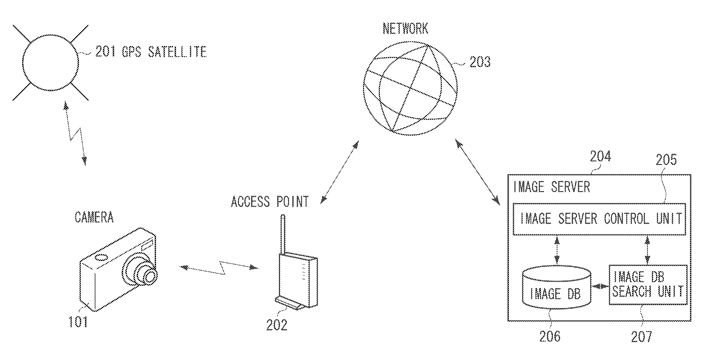
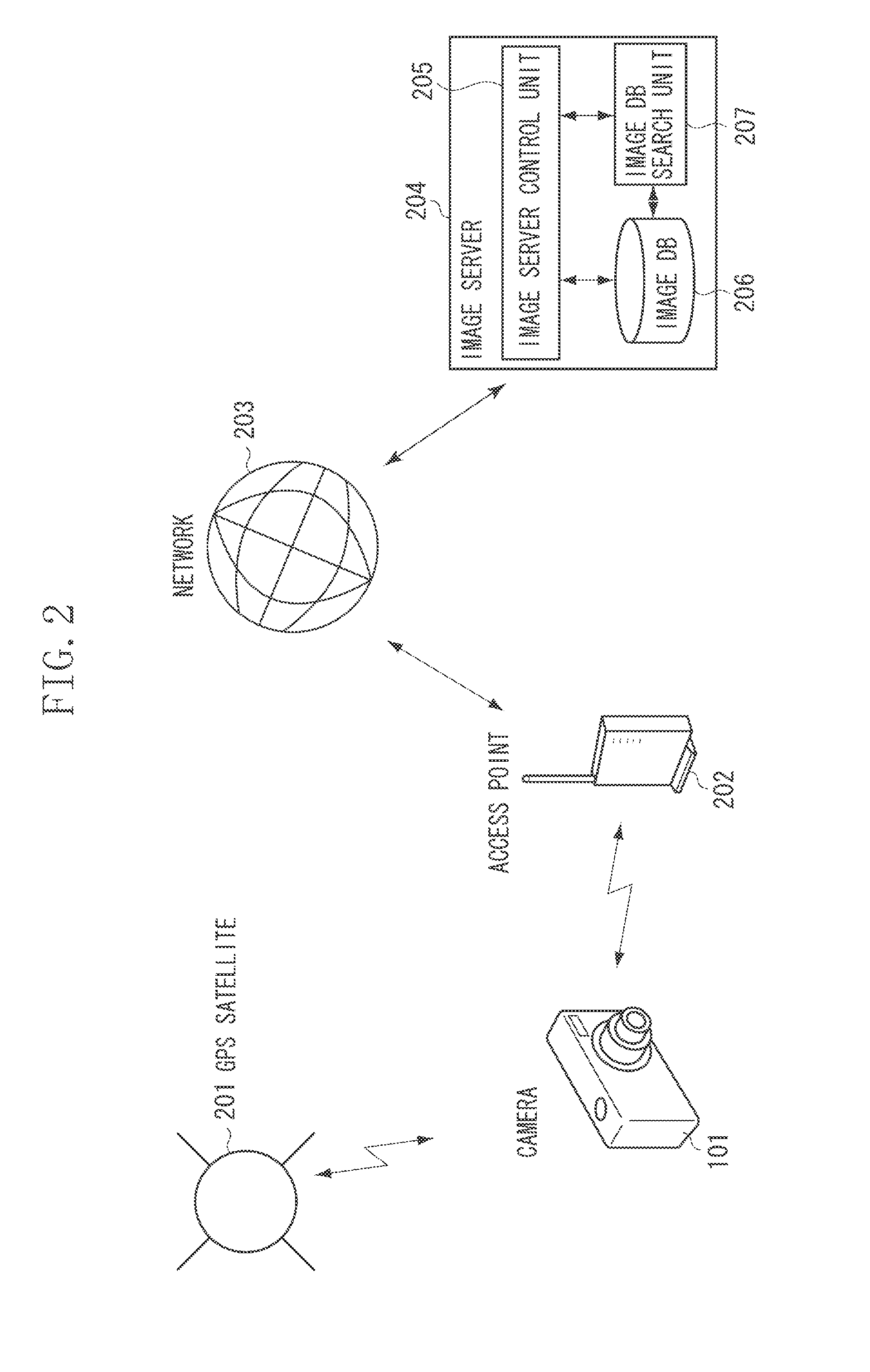
[0025]FIG. 2 illustrates a configuration of ...
PUM
 Abstract
Description
Claims
Application Information