Inverter System Having a Decoupling Switching Element

a switching element and inverter technology, applied in the field of inverter systems, can solve the problems of reducing internal semiconductor resistor loss, additional switching loss, etc., and achieve the effect of increasing the efficiency of inversion

Inactive Publication Date: 2012-05-10
ROBERT BOSCH GMBH
View PDF10 Cites 11 Cited by
  • Summary
  • Abstract
  • Description
  • Claims
  • Application Information

AI Technical Summary

Benefits of technology

[0013]The present invention is based on the finding that it is possible to increase the efficiency of an inversion using an inverter bridge having at least one switch by separating the inverter bridge from any energy source at the point in time at which the switch is switched over. This makes it possible for the at least one switch to be switched over energy free, whereby transient switching currents may be avoided. Immediately after the at least one switch is switched over, the inverter circuit is again connected to the energy source. This also avoids the charge reversal of the energy source, for example, a solar cell, as well as, if necessary, of a charging capacitor connected in parallel to it.
[0014]The present invention relates to an inverter system for converting a constant output signal of an energy-generating module, for example, a solar cell module having at least one solar cell, into an alternating current signal, having an input port for receiving the constant output signal from the energy-generating module, an inverter circuit connected downstream from the input port and provided for generating the alternating current signal by switching over at least one inverter circuit element and having a decoupling element, which is situated between the input port and the inverter circuit, it being possible for the decoupling switching element to be switched over immediately before the at least one inverter circuit element is switched over in order to decouple the at least one inverter circuit element from the input port at the point in time at which the inverter circuit element is switched over. This makes it possible to switch the inverter circuit element in an energy-free manner.

Problems solved by technology

However, the topologies described above have the disadvantage that when the particular switch is switched over, energy is fed into the capacitors and solar cells in the reverse direction, which reduces the efficiency of the inversion.
The internal semiconductor resistors are another source of loss.
Moreover, when the switches are switched over, additional switching losses occur, in particular at high clock frequencies, which at present may only be minimized by short-circuiting the particular bridge topology.

Method used


Image

  • Inverter System Having a Decoupling Switching Element
  • Inverter System Having a Decoupling Switching Element
  • Inverter System Having a Decoupling Switching Element

Examples


Embodiment Construction

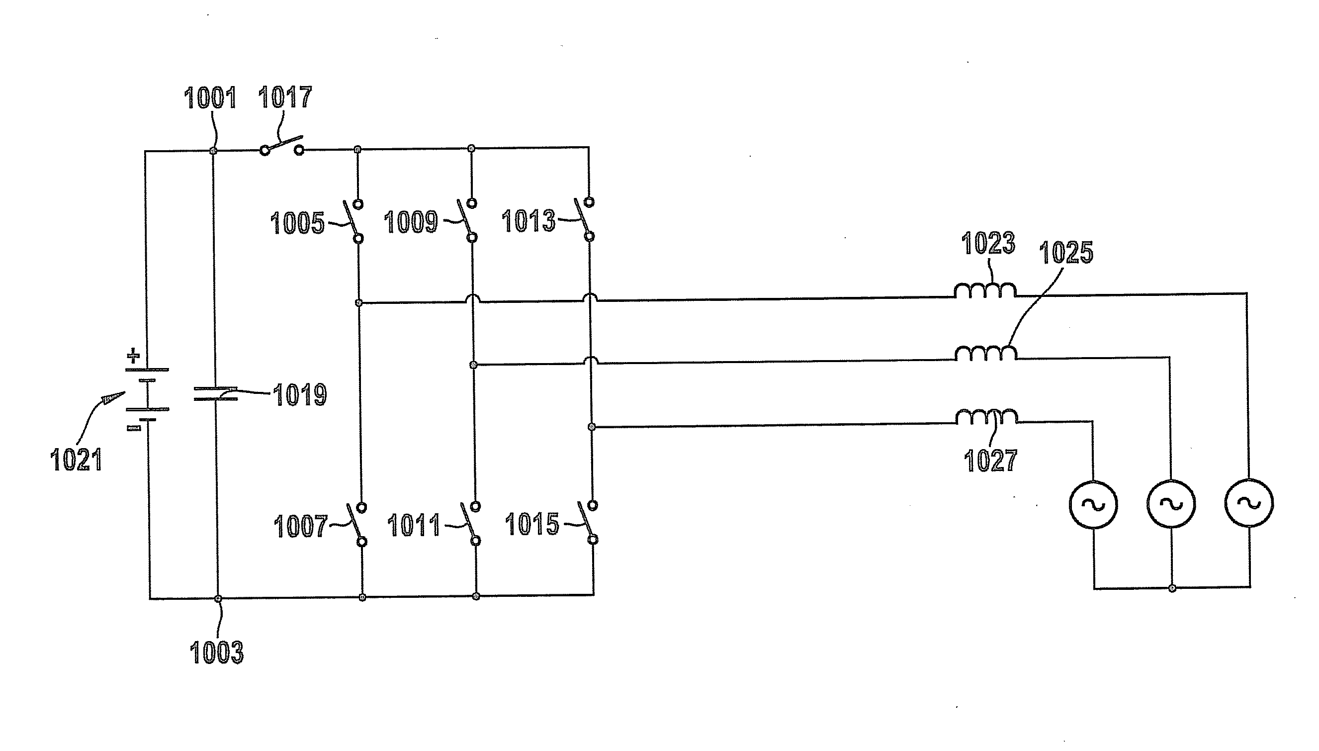
[0041]FIG. 10 shows an inverter system having an input port including terminals 1001 and 1003. An inverter circuit having switches 1005, 1007, 1009, 1011, 1013 and 1015 situated in series is connected downstream from the input port. A decoupling switching element 1017, for example, a transistor switch, is situated between the input port and the inverter circuit.

[0042]An energy storage 1019 and an energy-generating module 1021 are situated parallel to the input port and between terminals 1001 and 1003. Energy-generating module 1021 may, for example, be described by constant voltage sources connected in series and, for example, may be a solar system having at least one solar cell.

[0043]One pick-off each is situated between switches 1005 and 1007, 1009 and 1011, 1013 and 1015 connected in series in order to connect the inverter system to an energy distribution network connected downstream from it, the supply leads of which are, for example, described by inductors 1023.

[0044]For convert...


PUM


Abstract

An inverter system for converting a constant output signal of an energy-generating module, e.g., a solar cell module, into an alternating current signal, includes: an input port for receiving the constant output signal, an inverter circuit connected downstream from the input port and provided for generating the alternating current signal by switching over at least one inverter circuit element, and a decoupling switching element situated between the input port and the inverter circuit. The decoupling switching element is configured to be selectively switched over immediately before the at least one inverter circuit element is switched over in order to decouple the at least one inverter circuit element from the input port at the point in time of the switch-over.

Description

BACKGROUND OF THE INVENTION[0001]1. Field of the Invention[0002]The present invention relates to an inverter system for converting a constant output signal of an energy-generating module into an alternating current signal.[0003]2. Description of Related Art[0004]Inverters, in particular solar inverters, which may be designed as single-phase or three-phase units, are ordinarily used for the inversion of, for example, solar-generated energy. A basic circuit for a single-phase inversion is represented, for example, in FIG. 1, an H-bridge having four switches 101 being used for the inversion. The H-bridge is connected downstream from a solar cell 103, parallel to which a capacitor 105 is situated. The constant output signal of solar cell 103 is inverted using switches 101, each of which is switchable in pairs, and converted into an alternating current signal which is fed, for example, to an energy distribution network 107 via the pick-offs, each of which is situated between two switches...

Claims


Application Information

Patent Timeline
Patent Type & Authority Applications(United States)
IPC IPC(8): H02M7/48
CPCH02M7/53871
Inventor VOIGTLAENDER, KLAUS
Owner ROBERT BOSCH GMBH
Why Eureka
Try Eureka